Glowworm Energy 35 Store-A Скачать руководство пользователя страница 42

Index

42

Installation and maintenance instructions Energy 0020201109_01

Index

A

Air/flue pipe

Installing......................................................................... 12

Air/flue pipe, installed ............................................................ 4
Article number ....................................................................... 6

C

Calling up the fault memory................................................. 25
CE label................................................................................. 8
Check programmes ..................................................... 16, 28

Using.............................................................................. 16

Checking the burner ............................................................ 25
Checking the pressure in the heating water expansion
vessel .................................................................................. 22
Checking the pressure in the hot water expansion vessel ... 23
Cleaning the condensate siphon ......................................... 23
Cleaning the heat exchanger .............................................. 25
CO

content

Checking........................................................................ 18

Combustion air ...................................................................... 4
Completing inspection work ................................................ 25
Completing maintenance work ............................................ 25
Condensate drain pipework................................................. 12
Condensate siphon

Filling ............................................................................. 14

Controller............................................................................. 14
Corrosion........................................................................... 4

5

D

Decommissioning ................................................................ 26
Decommissioning the product ............................................. 26
Diagnostics codes

Using.............................................................................. 20

Documents ............................................................................ 6
Draining the product ............................................................ 22

E

Electricity ............................................................................... 4

F

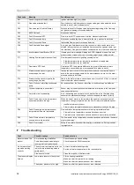
Fault codes.......................................................................... 25
Fault symbol ........................................................................ 16
Filling

Heating installation ........................................................ 16

Floor-standing oil-fired boiler................................................. 5
Flue gas route ....................................................................... 4
Front casing, closed .............................................................. 4
Frost ...................................................................................... 5

G

Grease................................................................................... 4

H

Heating installation

Filling ............................................................................. 16

I

Ice formation.......................................................................... 5
Identification plate ................................................................. 6
If you smell gas ..................................................................... 3
Inspection work ............................................................. 21, 27
Installation site....................................................................... 4
Intended use.......................................................................... 3

L

Lightning................................................................................ 5

M

Mains connection ................................................................ 14

Maintenance work ......................................................... 21, 27
Models and article numbers .................................................. 6

O

Opening................................................................................. 4

P

Power supply....................................................................... 14
Pump .................................................................................. 20
Pump output ........................................................................ 20

R

Regulating the bypass valve ............................................... 21
Regulations ........................................................................... 5
Removing the air intake pipe............................................... 24
Removing the burner........................................................... 24
Removing the flue pipe........................................................ 24
Removing the gas-air mixture unit....................................... 24
Removing the ignition transformer ...................................... 24

S

Safety device......................................................................... 4
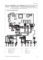
Schematic drawing ................................................................ 4
Seal ....................................................................................... 4
Serial number ........................................................................ 6
Solid fuel boiler...................................................................... 5
Sooting .................................................................................. 5
Spare parts.......................................................................... 21
Switching on the product ..................................................... 16

T

Tool ....................................................................................... 5
Transport ............................................................................... 4
Transporting .......................................................................... 8
Treating the heating water .................................................. 15

U

Unloading the box ................................................................. 8
Unpacking the product .......................................................... 8
Using

Check programmes ....................................................... 16
Diagnostics codes.......................................................... 20

V

Voltage .................................................................................. 4

W

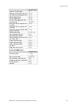
Weight ................................................................................... 9

Содержание Energy 35 Store-A

Страница 1: ...The energy you need Installation and main tenance instructions Energy 35 Store A H GB GB IE...

Страница 2: ...atio setting 17 6 11 Checking the gas flow rate 19 6 12 Checking function and leak tightness 20 7 Adapting the unit to the heating installation 20 7 1 Using diagnostics codes 20 7 2 Setting the pump o...

Страница 3: ...types follow the specifications in these in structions Intended use includes the following observance of accompanying operating installation and servicing instructions for the product and any other sy...

Страница 4: ...pipe 1 4 5 Risk of death due to explosive and flammable materials Do not use or store explosive or flammable materials e g petrol paper paint in the installation room of the product 1 4 6 Risk of deat...

Страница 5: ...n flue gas may pre cipitate as ice on the roof or the roof struc tures Ensure that this ice formation does not slide from the roof 1 4 15 Risk of fire and damage to electronics caused by lightning If...

Страница 6: ...dentification plate Meaning Serial number For quality control purposes 3rd and 4th digits year of production For quality control purposes 5th and 6th digits week of production For identification purpo...

Страница 7: ...ter plate heat exchanger 7 Temperature sensor at the domestic hot water cylin der s inlet 8 Temperature sensor at the domestic hot water cylin der s outlet 9 Diverter valve 10 Condensate siphon 11 Exp...

Страница 8: ...rder to pro tect your hands against sharp edges Ensure that you are carrying the load securely If required get somebody to assist you in this 4 1 2 Unloading the box from the delivery van It is recomm...

Страница 9: ...duct 1 Check whether the wall has sufficient load bearing ca pacity to bear the operational weight of the product Weight when filled with water Energy 35 Store A 118 kg 2 Check whether the supplied fi...

Страница 10: ...ion If non diffusion tight plastic pipes are used in the heating installation this may cause air to enter the heating water and corrosion of the heat generation circuit and the boiler If using non dif...

Страница 11: ...Ensure that the pipeline is visible 2 Connect the discharge pipe 1 for the heating expan sion relief valve 2 to a suitable draining mechanism A Make sure that the drain hose remains open to the surrou...

Страница 12: ...freeze and build into a larger ice plug As with other pipe work insulate the condensate dis charge pipe to minimise any risk of freezing and beware when crossing cavities that the fall is maintained...

Страница 13: ...te from header line systems must not drain into the boiler Length of the C43 type flue pipe Page 35 5 5 Electrical installation Danger Risk of death from electric shock The mains connection terminals...

Страница 14: ...e corresponding controller Power supply Single phase 230 V 50 Hz Fuse protection 3 A 4 Attach a plug to the mains connection cable 5 Connect the plug for the mains connection cable 6 Make sure that ac...

Страница 15: ...or above 10 0 clean the system and treat the heating water Ensure that oxygen cannot get into the heating water Page 20 Checking the filling and supplementary water Before filling the system measure...

Страница 16: ...ter and the heating function must be deactivated 6 7 Using check programmes By activating various check programmes you can trigger various functions on the product Check programmes Overview Page 28 6...

Страница 17: ...ting 50 2 Purge each radiator until the water escapes normally and then retighten the system s purging valves Conditions Difficulty purging the heating circuit Start the check programme P 06 Check pro...

Страница 18: ...tightness Close the gas isolator cock 1 Fit the panel Page 10 Disconnect the product from the power mains You must not start up the boiler Conditions Gas flow pressure in the permissible range End the...

Страница 19: ...gas flow rate 1 The gas flow rate depends on the CO content and the fan speed 1 2 2 Observe the information plate regarding the min 1 and max 2 rotational speeds on the air intake pipe 6 11 1 Checking...

Страница 20: ...on 7 1 Using diagnostics codes You can use the parameters marked as adjustable in the table of diagnostics codes to adapt the product to the system and customer requirements Overview of diagnostics co...

Страница 21: ...erefore strongly recommend that you install Glow worm original spare parts Information about available Glow worm original spare parts is available by contacting the contact address provided on the rev...

Страница 22: ...m 8 Create an air inlet by loosening the outlet connector 9 5 Removing and installing the air intake pipe Removing the air intake pipe Authorised compet ent person A 1 1 Unclip the air intake pipe 1 a...

Страница 23: ...ly with nitrogen otherwise with air The drain valve must be open during levelling Fill the hot water circuit Page 16 9 8 Checking the particle filter Note The particle filter must be removed and clean...

Страница 24: ...ixing screws 3 4 Carefully remove the electrode from the combustion chamber 5 Check whether the ends of the electrodes 5 are free from damage 6 Clean and check the gap between the electrodes Distance...

Страница 25: ...Troubleshooting Page 32 10 2 Rectifying faults If fault codes FXX appear refer to the table in the appendix for advice or use the check programmes Overview of fault codes Page 31 Check programmes Over...

Страница 26: ...persons Replace it in accordance with the recommendations for the power supply connection Page 14 Section of the mains power cable 3 G 0 75mm 11 Decommissioning the product Switch off the product Dis...

Страница 27: ...re correct and make any necessary adjustments X X 7 Close the gas isolator cock and the service valves X 8 Drain the product on the water side Check the pre charge pressure of the expansion vessel and...

Страница 28: ...es may not be visible for the product in question Setting level Values Unit Description Default setting User specific setting Min Max d 00 Maximum heating output kW The maximum heating output varies d...

Страница 29: ...ng flow temperature Not adjustable d 41 Heating return temperat ure Current value Displaying the heating return temperature Not adjustable d 43 Heating curve 0 2 4 Note This code is displayed if an ou...

Страница 30: ...S 24 Burner ignited S 25 Pump fan overrun S 26 Fan overrun S 27 Pump overrun S 28 Burner anti cycling time or lock against short cycles Special cases S 30 Room thermostat is blocking heating mode S 31...

Страница 31: ...Fault Gas valve without function Gas valve stepper motor not connected multiple plug on the PCB not plugged in correctly interruption in cable harness gas valve stepper motor defective electronics def...

Страница 32: ...ircuit to 5 V 24 V or internal fault in the water pressure sensor F 77 Fault Flue non return flap condensate pump No response from the flue non return flap or condensate pump defective F 79 Cylinder t...

Страница 33: ...12 4 13 5 14 6 15 7 16 8 17 9 18 1 2 3 4 10 9 8 7 6 5 4 3 2 1 19 20 18 17 16 15 14 13 12 11 M M T T T C NTC Ebus 24 V X2 X30 X90 X32 X40 X51 X31 X21 230 VAC L N X12 X101 FUS X14 X20 X18 X17 X17 1 4 2...

Страница 34: ...ning air bricks opening windows etc that can be opened 300 mm D Below temperature sensitive building components e g plastic gutters down pipes or wastewater pipes 75 mm E Below eaves 200 mm F Below ba...

Страница 35: ...t the condensate vapour plume does not damage adjacent surfaces a clearance of 300 mm is preferred For IE recommendations are given in the current issue of the IS 813 H 3 Opening of the flue pipe belo...

Страница 36: ...P 8 7 35 7 kW Maximum heat input heating Q max 30 6 kW Minimum heat input heating Q min 8 7 kW Maximum heat input hot water Q max 35 7 kW Minimum heat input hot water Q min 8 7 kW Technical data G31...

Страница 37: ...G20 13 8 g s Smoke mass flow in hot water handling mode at P max G20 16 1 g s Released system types C13 C33 C43 Nominal efficiency at 80 60 C 97 9 Nominal efficiency at 50 30 C 106 3 Nominal efficienc...

Страница 38: ...Energy 0020201109_01 J Commissioning Checklist Heating and Hotwater Industry Council HHIC www centralheating co uk Benchmark Commissioning and Servicing Section It is a requirement that the boiler is...

Страница 39: ...the appropriate Building Regulations and then handed to the customer to keep for future reference GAS BOILER SYSTEM COMMISSIONING CHECKLIST CONTROLS Optimum start control Fitted Fitted Fitted Fitted A...

Страница 40: ...ystem is serviced regularly and that the appropriate Service Interval Record is completed Service Provider SERVICE RECORD SERVICE 01 AND AND SERVICE 02 AND AND SERVICE 03 AND AND SERVICE 04 AND AND SE...

Страница 41: ...ecify how to set boiler to minimum rate contact Technical Helpline for advice CHECK CO AND COMBUSTION RATIO AT MINIMUM RATE With boiler still set at minimum rate insert analyser probe into flue gas sa...

Страница 42: ...t codes 25 Fault symbol 16 Filling Heating installation 16 Floor standing oil fired boiler 5 Flue gas route 4 Front casing closed 4 Frost 5 G Grease 4 H Heating installation Filling 16 I Ice formation...

Страница 43: ......

Страница 44: ...JT Telephone 01773 824639 Technical helpline 0330 100 7679 After sales service 0330 100 3142 www glow worm co uk These instructions or parts thereof are protected by copyright and may be repro duced o...

Отзывы: