


5 Installation
10
Installation and maintenance instructions Energy 0020201109_01
4.9
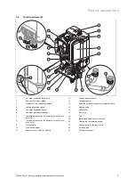
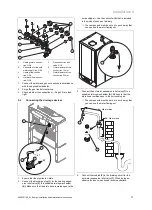
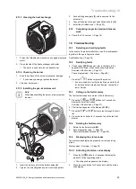
Removing and installing the front casing
Removing the casing
T20
B
A
A
1.
Follow the instructions in the specified sequence.
Installing the casing
2.
Refit the components in the reverse order.
5
Installation
Danger!
Risk of explosion or scalding caused by
incorrect installation.
Stresses in the supply line can cause leaks.
▶
Make sure there is no voltage in the sup-
ply lines when they are installed.
Caution.
Risk of damage caused by contaminated
lines.
Foreign bodies, such as welding remnants,
sealing residue or dirt in the water pipes, may
cause damage to the boiler.
▶
Flush the heating installation thoroughly
prior to installation.
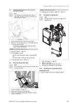
5.1
Connecting the gas and water pipes
Caution.
Risk of damage caused by incorrect gas
connection installation.
Excess test pressure or operating pressure
may cause damage to the gas valve.
▶
Check the gas connection for leak-tight-
ness.
Caution.
Risk of damage caused by corrosion.
If non-diffusion-tight plastic pipes are used in
the heating installation, this may cause air to
enter the heating water and corrosion of the
heat generation circuit and the boiler.
▶
If using non-diffusion-tight plastic pipes
in the heating installation, separate the
system by installing an external heat ex-
changer between the boiler and the heat-
ing installation.
Caution.
Risk of material damage due to heat trans-
fer during soldering.
▶
Do not solder the connection pieces if
the connection pieces are screwed to the
service valves.
Note
When installing in an unheated area, we recom-
mend that you provide thermal insulation for the
water pipe spigots on the boiler's outlet and on the
system.
Preliminary work
1.
Install the following components:
–
A stop cock in the cold water supply
–
A stop cock in the gas line
2.
Check that the system volume and the volumetric capa-
city of the expansion vessel are the same.
–
Expansion vessel capacity: 12 l
▽
If the volume of the expansion vessel is insufficient
for the system, install an additional expansion ves-
sel, connected as close to the product as possible,
in the heating return.
3.
Blow or flush the supply lines thoroughly prior to install-
ation.
Содержание Energy 35 Store-A
Страница 1: ...The energy you need Installation and main tenance instructions Energy 35 Store A H GB GB IE...
Страница 43: ......


