


Supplied By www.heating spares.co Tel. 0161 620 6677
36
221679H
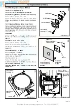
14 Replacement of Parts
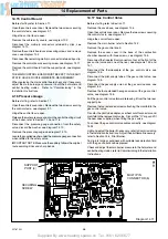
14.15 Control Board
Before starting refer to Section 11.
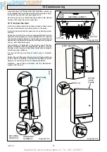
Open the controls cover door. Remove the two screws securing
the controls facia, see diagram 9.1.
Hinge the control fascia open.
Remove the cable entry covers, see diagram 10,2.
Disconnect the multi-pin connectors retained by clips, see
diagram 14.10.
Remove the controls board cover securing screws and remove
cover, see diagram 10.2.
Disconnect the remaining multi-pin connector retained by a clip.
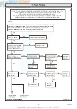
Remove the control board securing screw, see diagram 14.11.
Remove the control board from the support posts, see diagram
14.11.
THE MAIN CONTROL BOARD MUST BE KEPT IN THE ANTI
STATIC HOLDER UNTIL IMMEDIATE REQUIREMENT.
When replacing the main control board check and if necessary
adjust the main burner gas pressure in both the hot water and
central heating modes. Refer to “Commissioning” in the
Installation Instructions.
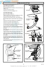
4.16 Pressure Gauge
Before starting, refer to Section 11.
Open the controls cover door. Remove the two screws securing
the controls facia, see diagram 9.1.
Hinge the control fascia open.
Release the water pressure and drain the central heating circuit
of the boiler, refer to Section 11.3 and 11.6.
Disconnect the pressure gauge connection from the safety
valve, discard the washer, see diagram 14.12.
Remove the pressure gauge, see diagram 14.13.
Locate the supplied washer under the pressure gauge connection
when refitted to the safety valve.
IMPORTANT NOTE: Make sure the capillary follows the original
route avoiding kinks and sharp bends.
7238
Diagram 14.11
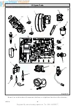
14.17 Gas Control Valve
Before starting refer to Section 11.
Remove the case base, see diagram 10.4.
Open the controls cover door. Remove the two screws securing
the controls facia, see diagram 9.1.
Hinge the control fascia open.
Remove the main burner refer to Section 14.2.
Remove the gas control knob.
Remove the access cover in the base of the combustion
chamber secured with three screws, see diagram 14.5.
Disconnect the five electrical connectors, four at the front of the
gas control valve and one at the rear, see diagrams 14.5 and
14.7.
Disconnect the thermocouple at the gas control valve, see
diagram 14.5.
Disconnect the pilot supply tube at the gas control valve, see
diagram 14.5.
Disconnect the gas supply union at the gas service cock, see
diagram 8.4.
Remove the four extended hexagon screws at the gas control
valve, see diagram 14.5.
Pull the gas control valve forward releasing it from the two rear
support pins.
Remove the four extended screws attaching the manifold to the
gas control valve
Transfer the pilot tube adapter, overheat cutoff connectors and
manifold to the replacement valve. Discard the “O” rings and fit
the new ones supplied, when fitting the gas valve.
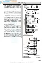
To connect the gas control valve cables correctly, see diagram
14.25.
Light and adjust the boiler if necessary, refer to Commissioning
in the Installation Instructions. Adjust the pilot flame if necessary,
refer to Section 14.4, Pilot Burner.
Test joints for gas soundness with suitable leak detection fluid
with the gas control knob depressed.
Check and adjust the main burner pressure in the hot water and
central heating modes, refer to Commissioning in the Installation
Instructions.
SUPPORT
POST (4)
SECURING
SCREW
MULTI PIN
CONNECTOR (5)


