


Supplied By www.heating spares.co Tel. 0161 620 6677
14
221679H
TOP STD.
REAR
SIDE
TOP EXTD.
REAR
SIDE
MINIMUM
WALL
THICKNESS
MINIMUM
FLUE
LENGTH
MAXIMUM
FLUE
LENGTH
"Y"
BOILER MOUNTING FACE
TO EXTERNAL WALL FACE
"X"
BOILER CASING TO
EXTERNAL WALL FACE
MAXIMUM DISTANCE FROM
126
212
519
-
-
438
75
75
75
75
126
212
840
840
789
-
-
708
570
570
FLUE
PACKS
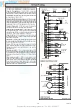
NOTE :
IF IT IS NECESSARY TO CUT THE DUCTS
TO ACHIEVE THE "FLUE LENGTH" MAKE SURE
THAT THE OVERLAPS ARE AS FOLLOWS :-
THE OVERLAP FOR AIR DUCT = 25mm
THE OVERLAP FOR FLUE DUCT = 50mm
THE MAXIMUM LENGTHS CAN BE INCREASED
BY AN ADDITIONAL 3 METRES WITH THE USE
OF THE 1 METRE EXTENSION KITS.
NOTE :
THIS APPLIES TO STANDARD KITS ONLY.
REAR FLUE
SIDE FLUE
15mm
VIEW ’B’
VIEW ’B’
15mm
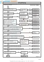
STD./EXTD. TOP OUTLET FLUE PACK & 1 METRE EXTENSION KIT
SCREW
& TAPE
SCREW
& TAPE
SCREW
& TAPE
SCREW
& TAPE
3 x 1 metre extension kits may be joined together.
FLUE LENGTH
MAX 840mm (extd.)
MAX 570mm (std)
FLUE LENGTH
MAX 840mm (extd.)
MAX 570mm (std)
15mm
SCREW
& TAPE
117mm
36mm
TOP OUTLET FLUE PACK
’X’
’X’ plus 132mm = FLUE LENGTH
SIDE FLUE ’X’ plus 132mm = FLUE LENGTH
REAR FLUE ’Y’ plus 50mm = FLUE LENGTH
’Y’
’X’
’Y’ plus 50mm = FLUE LENGTH
’Y’
C
L
C
L
Diagram 7.1
7508
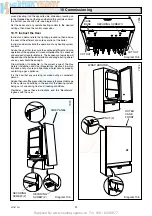
7 Flue Preparation
7506
7.1 Flue Position and Length
Determine flue application, length and terminal position before
starting, refer to diagram 7.1.
Note: The Standard Top Outlet Flue Pack and the Extended
Top Outlet Flue Pack contains a flue duct extension piece
complete with "O" rings, this should be discarded.
If you are using a Flue Bend or a Vertical Flue Kit, please follow
the instructions supplied with the kit.
To make a neat finish to the flue outlet a flue collar kit, part No.
443286, with instructions, is available, see diagram 7.2.
Note: If required an optional wall liner kit, part no. 900862, is
available complete with instructions.
7.2 Flue Assembly
Extend the telescopic flue to the required length, making sure
that the minimum overlap is no less than 25mm, and that the flue
terminal projects 15mm minmum beyond wall face, see diagram
7.1.
Carefully drill though air duct pilot hole and secure with self
tapping screw provided in fittings pack, see diagram 7.1.
Seal the joint with the tape provided.
If the flue system requires the addition of flue extension kits,
drill, seal and secure them with the self tapping screw and tape
provided.


