Supplied By www.heating spares.co Tel. 0161 620 6677
34
221679H
14 Replacement of Parts
14.6 Pilot Injector
Before starting, refer to Section 11.
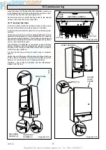
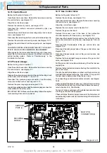
Remove the sealing angle, secured with a single screw, see
diagram 14.2.
Remove the spark electrode, secured with a spring clip, see
diagram 14.2.
Disconnect the thermocouple nut from the pilot burner.
Disconnect the pilot supply tube, holding the pilot injector
hexagon with another spanner, then remove the pilot burner.
Remove the pilot injector from the pilot assembly by unscrewing
it.
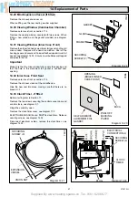
Check the pilot flame length on relighting, see diagram 14.4.
Test pilot for gas soundness with suitable leak detection fluid
with the gas control knob depressed.
14.7 Thermocouple
Before starting refer to Section 11.
Open the controls cover door. Remove the two screws
securing the controls facia, see diagram 9.1.
Hinge the control fascia open.
Remove the main burner, refer to Section 14.2.
Remove the sealing angle secured with a single screw, see
diagram 14.2.
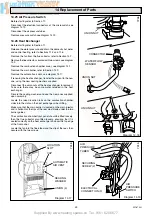
Remove the access cover in the base of the combustion
chamber secured with three screws, see diagram 14.5.
Disconnect the thermocouple at the gas control valve and pilot
assembly, see diagram 14.2 and 14.5.
Remove the thermocouple.
Make sure that the overheat cut-off connector is in place in the
slot of the gas control valve when fitting the thermocouple. Do
not tighten the thermocouple nut more than a quarter turn
beyond finger tight or make any tight bends in the thermocouple
capillary.
Test joints for gas soundness with suitable leak detection fluid
with the gas control knob depressed.
14.8 Central Heating Boiler Overheat Cut-off
Before starting refer to Section 11.
Open the controls cover door. Remove the two screws
securing the controls facia, see diagram 9.1.
Hinge the control fascia open.
Disconnect the overheat cut-off electrical connectors positioned
at the front and rear of the gas control valve, see diagrams 14.5
and 14.7.
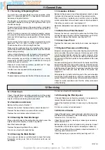
Unclip to remove the overheat cut-off, see diagram 14.8.
14.9 Domestic Hot Water Boiler Overheat
Cut-off
Before starting refer to Section 11.
Open the controls cover door, see diagram 4 user instructions.
Remove the two screws securing the controls facia, see
diagram 9.1.
Hinge the control fascia open.
Disconnect the overheat cutoff electrical connectors, see
diagram 14.8.
Remove the securing screws to release the overheat cut-off.
14.10 Domestic Hot Water Thermistor.
Before starting, refer to Section 11.
Open the controls cover door. Remove the two screws securing
the controls facia, see diagram 9.1.
Hinge the control fascia open.
Disconnect the electrical connector at the domestic hot water
thermistor, see diagram 14.8.
Unclip the domestic hot water thermistor from the flow pipe.
14.11 Central Heating Hot Water Thermistor.
Before starting, refer to Section 11.
Open the controls cover door. Remove the two screws securing
the controls facia, see diagram 9.1.
Hinge the control facia forward.
Disconnect the electrical connector at the domestic hot water
thermistor, see diagram 14.8.
Unclip to remove the domestic hot water thermistor from the
flow pipe.
14.12 Transformer
Before starting, refer to Section 11.
Open the controls cover door. Remove the two screws securing
the controls facia, see diagram 9.1.
Hinge the control fascia open.
Disconnect the inline electrical connectors from the transformer,
see diagram 14.8.
Remove the transformer, noting the correct position.
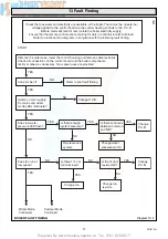
To connect the transformer cables correctly, see diagram
14.25.
14.13 Fan Resistor
Before starting, refer to Section 11.
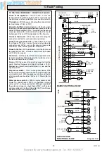
Disconnect the electrical connectors from the resistor, see
diagram 14.6.
Remove the resistor, noting the correct position.
To connect the resistor cables correctly, see diagram 14.25.
14.14 Piezo Unit
Before starting refer to Section 11.
Open the controls cover door. Remove the two screws securing
the controls facia, see diagram 9.1.
Hinge the control fascia open.
Disconnect the ignition and earth leads at the piezo unit.
Remove the piezo unit, see diagram 14.9.


