


Supplied By www.heating spares.co Tel. 0161 620 6677
33
221679H
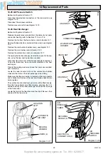
Disconnect the pilot supply tube, holding the pilot injector
hexagon with another spanner, then remove the pilot burner.
Check the spark gap upon assembly, see diagram 14.4.
Make sure the pilot injector is fitted.
Test joints for gas soundness with suitable leak detection fluid
with the gas control knob depressed.
14.5 Spark Electrode
Before starting, refer to Section 11.
Slacken the sealing angle, secured with a single screw, see
diagram 14.2.
Remove the spark electrode, secured with a spring clip, see
diagram 14.2.
Ease the spark electrode through the sealing angle.
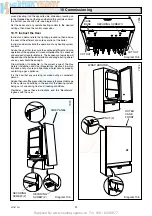
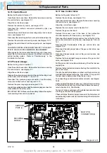
Open the controls cover door. Remove the two screws securing
the controls facia, see diagram 9.1.
Hinge the control fascia open.
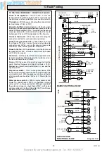
Disconnect the ignition lead from the piezo unit, see diagram
14.9.
Check the spark gap upon the assembly, see diagram 14.4.
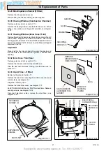
14 Replacement of Parts
Diagram 14.4
SPARK GAP 4.5mm
to 5.5mm
FLAME
LENGTH
25mm
4574
Diagram 14.3
7311
COPPER
WASHER
MAIN
INJECTOR
7079
Diagram14.5
ACCESS
COVER
SECURING
SCREW (3)
SHORT SECURING
SCREW (2)
LONG SECURING
SCREW (2)
PILOT TUBE
NUT
THERMOCOUPLE
NUT
OVER HEAT
CUTOFF
ELECTRICAL
CONNECTION
OVER HEAT
CUTOFF
SHORT SECURING
SCREW (2)
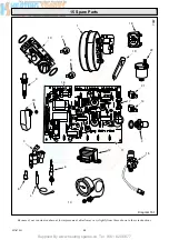
WARNING
230V 50Hz
ELECTRICAL
CONNECTION (5)
GAS
CONTROL
VALVE


