26
Visit our website at http://www.globalhobby.com or for Customer Service at http://globalservices.globalhobby.com
❑
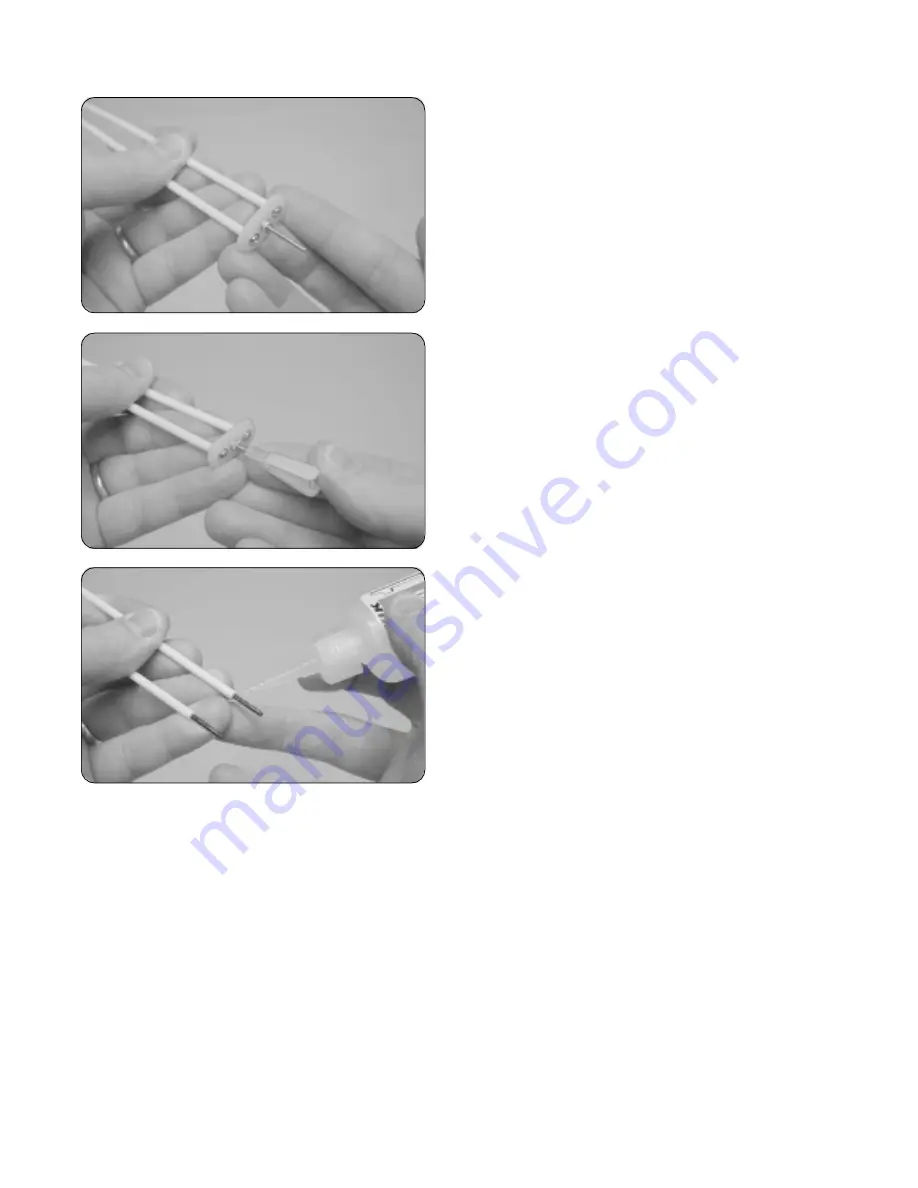
Secure both 23-3/4" long pushrod tubes to the back of
the nylon joiner plate using two 2mm x 10mm wood screws
and two 2mm flat washers.
☞
Be sure to tighten the screws firmly.
❑
Apply a drop of thin C/A to each pushrod tube where it
attaches to the joiner plate. The C/A will "wick" down into the
tube, locking the wood screws into place. Do not omit
this procedure.
❑
Thread one nylon clevis onto the machine screw.
IMPORTANT
Make sure the clevis is threaded on completely,
so there's no chance of it coming loose.
❑
Slide the plain end of one 5-7/8" long threaded pushrod
wire into the back of each nylon pushrod tube.
❑
Thread the wires into the tubes until 1/2" of threaded wire
extends past the end of each tube.
❑
Apply a couple of drops of thin C/A to the ends of the
tubes. The C/A will "wick" into the tubes, securing the wires
firmly in place.
Do not omit this procedure.
❑
Using a modeling knife, cut away and remove the covering material from over both elevator pushrod exit holes. One
hole is located in each side of the fuselage, 6-3/4" in front of the rudder hinge line and 1-3/8" above the bottom of
the fuselage.
❑
Using a modeling knife, carefully cut away all but one arm from a large "4-point" servo horn.
❑
Snap the nylon clevis (attached to the joiner plate assembly) into the
third hole
out from the center of the servo arm.
☞
You will have to enlarge the hole in the servo arm using a 5/64" drill bit so the clevis does not bind.
❑
Connect your radio system and plug the elevator servo lead into its proper slot in the receiver. Double-check that the
elevator trim lever on your transmitter is centered.
☞
The elevator servo is the servo on the right side of the fuselage, behind the throttle servo.
Step 2: Installing the Elevator Pushrod Assembly


