z
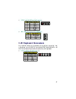
CN20: LVDS Connector
PIN Description PIN Description
1
VCC3
2
VCC3
3
Y6
4
Y3
5
Y1
6
Y0
7
Y4
8
Y2
9
Y7
10
Y5
11
GND
12
GND
VCC3
Y6
Y1
Y4
Y7
GND
1
2
VCC3
Y3
Y0
Y2
Y5
GND
z
JP27: Panel Voltage Select
PIN Description
11
12
1 3
1-2
+5V
2-3 (default)
+3.3V
3.9 PCI E-IDE Drive Connector
CN4
and
CN3
are standard 40-pin connectors daisy-chain driver
connector serves the PCI E-IDE drive provisions onboard the 3301320.
A maximum of four IDE drives can connect to
CN4
and
CN3
.
z
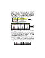
CN4: Primary IDE Connector
PIN Description PIN Description
1
RESET
2
GND
3
PDATA7
4
PDATA8
5
PDATA6
6
PDATA9
7
PDATA5
8
PDATA10
9
PDATA4
10
PDATA11
11
PDATA3
12
PDATA12
13
PDATA2
14
PDATA13
15
PDATA1
16
PDATA14
17
PDATA0
18
PDATA15
19
GND
20
N/C
21
PDREQ
22
GND
23
PIOW#
24
GND
25
PIOR#
26
GND
27
PIORDY
28
470
to GND
29
PPDACK#
30
GND
31
Interrupt
32
N/C
33
PDA1#
34
PATA66
. . . More on next page . . .
13
Содержание 3301320
Страница 1: ...User s Manual 3301320...
Страница 8: ...1 3 Board Dimensions 4...
Страница 12: ...3 2 Board Layout NOTE JP8 only for use Intel 82559 if you want to use Intel 82559 please set JP8 short 1 2 8...
Страница 59: ...2 Specify the path of the new driver and then press on Enter If in driver D type d Vga Via_8606 Nt40 55...
Страница 66: ...2 Select the operating system of your computer to proceed with the installation process 62...


