background image


19 

Table A - 2.3. Control Designations:  Labeled as P5 on servo drive 


Table A - 2.4. Wye/Delta Designations:  Labeled as P6 on servo drive 


Table A - 2.5. Control and Wye/Delta Connectors 


A - 3. Encoder Input Connector


Table A - 3.1. Encoder Input Designations:  Labeled as P4 on servo drive. 


Table A - 3.2. Encoder Input Connector 


Designations 

Pin# 

I/O 

Name 

Function 

1  

Input 

Shield 

Cable Shield 

2  

Power 

+5V 

E5VDC out, 150mA max 

Power 

GND 

Encoder Power Return 

Input 

B - 

Encoder Channel B - (not) 

Input 

B + 

Encoder Channel B + 

Input 

Index + 

Encoder Index + (Channel Z +) 

Input 

A + 

Encoder Channel A + 

Input 

A - 

Encoder Channel A - (not) 

Input 

Index - 

Encoder Index - (Channel Z -) 

Designations 

Pin# 

I/O 

Name 

Function 

1  

Input   Spindle Common 

Spindle Common (for Forward & 

Reverse) 

2  

Input   *Spindle Reverse  

Spindle Reverse 

3  

Input   *Spindle Forward 

Spindle Forward 

4  

Input  

CMD Common 

CMD Common (for Fault & Speed) 

5  

Input/

Output 

*ESTOP/ 

*Spindle Fault 

Emergency Stop/Spindle Fault 

Output 

Spindle Speed 

Spindle Speed Command 


Connector 

Description/Type 

6-Pin Male Mating 

Connector Housing 

Female Crimp Terminal 

Receptacle, 6 Position, 

22-18 AWG 

Molex 03-09-1064 

Molex 02-09-1119 

Designations 

Pin# 

I/O 

Name 

Function 

1  

Input  

Wye/*Delta 

Wye or Delta modes 

2  

N/C  

Reserved 

Reserved 

3  

Input   Hi Gain/*Lo Gain 

High Gain or Low Gain modes 

4  

Input  

Common 

Common for Wye/Delta and 

High Gain/Low Gain modes 

5  

N/C 

Reserved 

Reserved 

N/C 

Reserved 

Reserved 

Connector 

Description/Type 

9-Pin Male Mating 

Connector Housing 

Female Crimp Terminal 

Receptacle, 9 Position, 

22-18 AWG 

Molex 03-06-1092 

Molex 02-06-1103 

Содержание SMB9675-1A-1

Страница 1: ...L Model SMB9675 1A 1 MANUAL 9675 1040 000 REVISION B DATE 9 Sep 2011 FADAL REPLACEMENT SENSORED VECTOR DRIVE SENSORLESS INVERTER DRIVE Fadal is a trademark of Fadal Machining Centers we have no affili...

Страница 2: ......

Страница 3: ...Cable 8 3 3 3 Control Cable 8 3 3 4 Wye Delta Cable 8 3 3 5 Encoder Feedback Cable 8 3 3 6 Rigid Tap Cable Encoder Output 8 CHAPTER FOUR SETUP AND TUNING 4 1 Turning the power on 10 4 2 Establishing...

Страница 4: ...and Signal 22 Controller Inputs Outputs 22 Encoder Feedback 24 Encoder Output 24 Load Meter Output 24 PC Interface 25 Power Input and Motor Output 26 DRAWINGS DIAGRAMS FADAL Vector Drive Installation...

Страница 5: ...control down to and including zero speed of an induction motor The SMB9675 1A 1 vector drive can operate in sensorless mode no feedback is needed This mode of operation is usually referred to as inver...

Страница 6: ...LDOR 15HT 7 5K YD 7500 15 SMB9675 1A 1 7090 INV 0044 VECTOR BALDOR 10HP 7 5K YD CE 7500 10 SMB9675 1A 1 7090 INV 0045 VECTOR BALDOR 10HP 7 5K YD 10K 7 5K 10 SMB9675 1A 1 7090 INV 0046 VECTOR BALDOR 15...

Страница 7: ...ALDOR 10HP 10K NCL NON RT 10000 10 SMB9675 1A 1 7091 INV 0054 INVERTER BALDOR 15HT 10K NCL NON RT 10000 20 SMB9675 1A 1 7091 INV 0057 INVERTER BALDOR 5HP 6500RPM 6POLE 6500 5 SMB9675 1A 1 7091 INV 003...

Страница 8: ...l work with Glentek Inc vector or VFD drives earlier versions are not compatible 2 2 3 Installation The MotionMaestro install disk is set up to utilize Install Shield to simplify installation There ar...

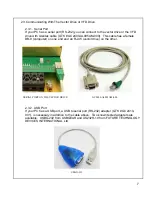
Страница 9: ...cable has a female DB 9 computer on one end and an RJ 45 vector drive on the other 2 3 2 USB Port If your PC has a USB port a USB to serial port RS 232 adapter GTK GC2410 001 is necessary in addition...

Страница 10: ...ecting the AC regenerative braking motor and green ground wires Match the wire labels to the terminal block labels Check connections for tightness See the Appendix A for more details 3 3 2 Load Meter...

Страница 11: ...Before and after photos of a typical installation 9...

Страница 12: ...se the procedures as follow for reference 4 1 Turning the Power On Carefully recheck the wiring Restore power to the VMC After the VMC is finished initializing check the vector drive status 7 segment...

Страница 13: ...motor to be used The Nominal DC Bus is preset to 325VDC Motor Safety Limits Verify that the value is same as motor rating Vector Control Parameters Verify that the parameters are correct and match th...

Страница 14: ...amplifier the parameters need to be saved to NVM Non Volatile Mem ory The saving sequence is amplifier model part number dependent Refer to the appropriate amplifier model part number below for the ne...

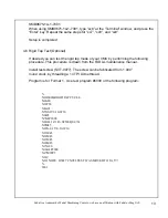
Страница 15: ...tenance manual Install test screw SVT 0077 The screw can be fabricated from 1 000 round stock by threading a 14 TPI Acme thread Program is for Format 1 Use test program 6000 or the following program N...

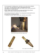
Страница 16: ...the SINGLE STEP key Be sure the test screw returns to its original position Set the indicator as shown below the tip must be touching the lower thread halfway into the thread the second thread from th...

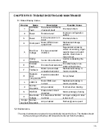
Страница 17: ...450VDC Regenerative braking circuit not working regen resistor does not match spindle check fuse in regen circuit C Clamp Disabled Vector drive disabled Control is disabling the drive E Encoder Fault...

Страница 18: ...ge caused by such product or part Under no circumstances shall Glentek Inc or any of our affiliates have any liability whatsoever for claims or damages arising out of the loss of use of any product or...

Страница 19: ...n charged after the power is shutoff Wait 5 minutes to allow the capacitors to discharge before removing the cover or working on the drive Be sure the system is properly grounded before applying power...

Страница 20: ...LINE 1 three phase AC input 2 Input L2 AC LINE 2 three phase AC input 3 Input L3 AC LINE 3 three phase AC input 4 Rsvd Reserved Reserved 5 Rsvd Reserved Reserved 6 Output B DC BUS Return output 7 Inpu...

Страница 21: ...unction 1 Input Spindle Common Spindle Common for Forward Reverse 2 Input Spindle Reverse Spindle Reverse 3 Input Spindle Forward Spindle Forward 4 Input CMD Common CMD Common for Fault Speed 5 Input...

Страница 22: ...nal wiring 22 AWG 0 326 mm2 or larger 105 C rated PVC or better Connector Description Type 5 Pin Terminal Block Terminal Block 5 Position 22 12 AWG Phoenix Contact 1934890 Designations Pin I O Name Fu...

Страница 23: ...acters will be displayed as is appropriate to the fault or state Note See Chapter 5 for more information on Amplifier status codes Controller Input and Output Signals Signals that typically are connec...

Страница 24: ...rection If both signals are on the signals are pulled low motor movement in both directions is enabled When only one enable is closed FORWARD or REVERSE on the velocity command is unipolar and when bo...

Страница 25: ...O pin at the amplifier A spindle FAULT is de clared by the spindle drive Status good is 10 VDC thru a 1K pull up resistor 0 VDC indicates a fault condition to the CNC The Fault output is open collecto...

Страница 26: ...of up to 10 MHz is possi ble but is system dependent The Z channel is edge sensitive such that swapping Z and Z does not change the behavior of the amplifier Encoder Output The encoder out signals are...

Страница 27: ...ector Note If required Glentek can customize a serial port digital interface to adapt to your controller as re quired to meet your protocols We are currently doing this for high speed Ethernet ports 2...

Страница 28: ...VDC 5 R1 and R2 are external Regen resistor brake inputs Acceptable resistance range is 12 30 Ohms Regen turns on at 430 VDC 5 Regen circuit uses a Ferraz Shawmut TRS10R time delay fuse Motor power is...

Страница 29: ...27 Fadal is a trademark of Fadal Machining Centers we have no affiliation with Fadal or Mag IAS...

Страница 30: ...28...

Страница 31: ...29...

Страница 32: ...t MM Set Trajectory Slew Rate Generator Amps Sec or RPM Sec AL DL MM View MM Set Analog Input Scale MM Set 32768 IAS Mode 1 Current Command SVC Velocity Limiter VL MM View MM Set Mode 2 Velocity Comma...

Страница 33: ...Velocity Control Loop Diagram Velocity Error MM Set MM Set MM Set Raw Velocity Estimate Proportional Gain MM Set 32768 GVP Integral Gain MM Set 32768 GVI Tach Gain MM Set 32768 GVF Derivative Gain MM...

Страница 34: ...conversion Park Transform Station Frame to Rotation Frame conversion Incremental Encoder MM View Sensored Vector Current Control Loop Diagram Rotor Time Constant VFT MM Set Induction Motor GLENTEK cus...

Страница 35: ......

Страница 36: ...208 Standard Street El Segundo California 90245 USA Telephone 310 322 3026 Fax 310 322 7709 www glentek com e mail sales glentek com...

Отзывы: