Glentek Inc. 208 Standard Street, El Segundo, California 90245, U.S.A. (310) 322-3026
54
Omega Series Digital PWM Amplifier Manual
to phase BEMF zero crossings. If the
Hall sensors are aligned with the motor’s
phase to neutral BEMF, then the commu-
tation offset angle must be set to ±30 de-
grees (you have to try both) before com-
paring the commands to the BEMF wave-
forms.
N)
Find the phase S motor lead.
In MotionMaestro
©
, change the Analog
Output Signal Source
S Current Com-
mand
. Place the channel 2 scope probe
on one of the two remaining motor leads.
Rotate the motor in the same direction
that was used for phase R above. Deter-
mine which of the remaining two leads of
the motor result in a waveform that is in
phase with the phase S command. Label
this lead Phase S. Move the channel 2
probe to the remaining motor lead.
O)
Find the phase T motor lead.
Same procedure as above with the analog
output source set to
T Current Command
.
If phase R and phase S where properly
found, phase T will be the remaining motor
wire. Label this lead phase T.
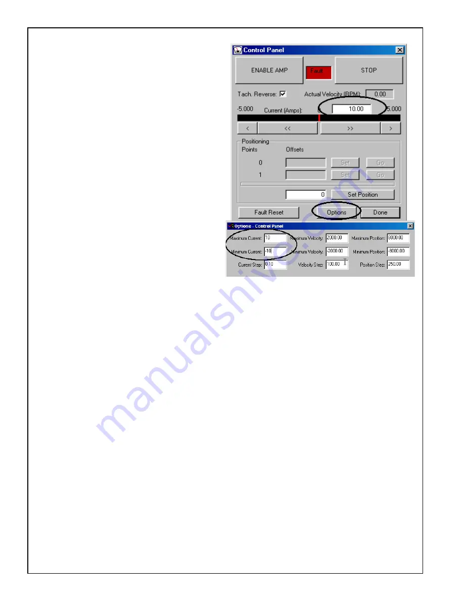
P) Set the current command back to
0 by clicking the STOP button on the Control Panel.
Re-
set any current limits, foldback thresholds to the desired operational settings. Reset the Control
Panel options to appropriately safe values. Set the Analog Input Signal Gain back to the de-
sired operational value.
Q) Save the settings by selecting “Save to NVM” from the Setup menu.
R) Remove the amplifier’s power. Remove the scope probes. Connect the motor R, S, and T
leads to the amplifier’s R, S, and T terminals respectively.
S) Apply power to amplifier. The amplifier should still be in
Current Mode
and
Enabled
(unless
the external inhibit is active). From the Control Panel, see following picture, issue a digital cur-
rent command of
0
.
5 to 2 amps
, enough so the motor begins to rotate.
T) While the motor is rotating, verify that the sign of the actual velocity matches the sign of the
commanded current. If NOT mark the
Tach Reverse
checkbox on the control panel and verify
that the signs now match. Command the opposite polarity current to the motor,
-.5 to -2.0
amps
and verify that the motor reverses direction and runs at approximately the same speed.
The signs of the current command and actual velocity should still match.
U) Set the current command back to 0 by clicking on the
STOP
button of the Control Panel. Save
the settings by selecting “Save to NVM” from the setup menu.
The motor should now be properly commutated and phased.
Содержание Omega SMC9930
Страница 73: ...Glentek Inc 208 Standard Street El Segundo California 90245 U S A 310 322 3026 73 Appendix K...
Страница 75: ...Glentek Inc 208 Standard Street El Segundo California 90245 U S A 310 322 3026 75 Appendix K...
Страница 77: ...Glentek Inc 208 Standard Street El Segundo California 90245 U S A 310 322 3026 77...


