C
ABLEMASTER
W
IRING
I
NSTRUCTIONS
(
CON
’
T
.)
T
HE
CM-7
AND
CM-8
POWER UNITS
are wired through an integral
relay assembly for 12 or 24 volt DC depending on your boat’s
voltage. The voltage for each
Cablemaster
is located on the unit’s
label. The
Cablemaster
should be connected to a separate circuit
breaker of appropriate amperage (see Fig. 9) on the main or aux-
iliary DC electrical distribution panel. In addition to providing elec-
trical “overload” protection, a separate breaker for the
Cablemaster
allows the unit to be turned “OFF” thus preventing
the unauthorized use of the unit when the boat is unattended.
This is especially important if the switch is located where it can
easily be actuated by children on board.
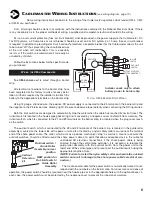
Be sure to observe the proper polarity when connecting the DC
imput wires.
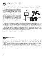
Both the limit switches are designed to automatically stop the
motor when the cable has reached it’s limit of travel. The in-limit
switch is located in the hawse pipe gasket ring and is covered by a neoprene cover to shield it from moisture. The in-limit
switch, which is connected to the #4 and #5 terminals on the relay assembly, is activated when the plug cover touches the
switch.
The out-limit switch, which is connected to the #6 and #7 terminals of the relay assembly, is located in the guide roller
assembly mounted on the lower side of the power unit and is activated by a nylon safety collar secured near the terminal
end of the shore power cable. The collar, which acts as a positive mechanical “stop” as well as a means to activate the
out-limit swithces, would be fitted around the shore power cable at a point that allows adequate slack in the cable for
unstrained AC electrical connections (The same collar is used for 6/3 or 6/4 cable). If the shore power cable is being direct-
ed through the vertical pipe extension, it is necessary to relocate the guide roller assembly with the out-limit switch from
the power unit to the lower end of the vertical pipe and to reconnect the out-limit switch using the appropriate lengths of
wire (NOTE: Failure to install the nylon safety collar and rewire the out-limit switch can result in damage to the shore power
cable’s electrical connection).
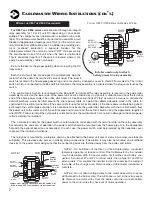
The 3 conductor cable for the power switch is color coded to correspond with the terminal strip on the relay assembly.
For convenience and ease of operation, the power switch should be mounted near the hawse pipe or in the appropriate
hole with the optional bezel (see accessories). In each case, the power switch must be protected by the neoprene cover
to prevent the intrusion of moisture.
The relay box is mounted on a sub-plate and may be attached to the power unit cover screws in two ways (see label on
sub-plate). This provides easy access in making wiring connections. If desirable, it may also be mounted on a bulkhead
close by to the power unit making sure that the connecting wires are fastened away from the pulley and rollers.
NOTE 1: On installation of the CM-7 or CM-8 Cablemaster, convenient
temporary operation or remote control of the Cablemaster by the installer
may be desirable. With the power switch, limit swithes and battery con-
nected, first jumper #1 and #2 to retract cable, then jumper #1 and #3 to
extend cable. This enables the installer to directly supervise the coiling of
the cable at the storage area. Remove when Cablemaster installation is
complete.
NOTE 2: Do not attach voltage wires to the motor wires while they are
still fastened to the barrier strip. This will cause a short in the relay assem-
bly. Remove the motor wires from the barrier strip then connect battery
power to the motor wires for check-out of motor operation.
D
12
7
W
IRING THE
CM-7
OR
CM-8 C
ABLEMASTER
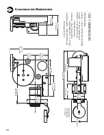
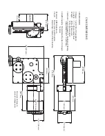
10"
(254mm)
13"
(330mm)
24"
(610mm)
13"
(330mm)
17-7/8"
(454mm)
6 1/2"
(165mm)
CM-4 DIMENSIONS
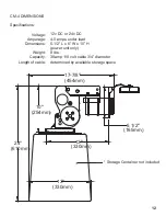
Specifications:
Voltage:
Amperage:
Dimensions:
Weight:
Capacity:
Length of cable:
12v DC or 24v DC
4-5 amps under load
5-1/2” L x 6” W x 10” H
(power unit only)
9 lbs.
30amp 110 volt cable 3/4” diameter
determined by available storage space
* Storage Container not included
Red 1
White 2
Black 3
Power
Switch
Pos. +
Neg. -
12 / 24v
DC Input
Motor
Output
CABLEMASTER RELAY ASSEMBLY
# 04034 (12, 24 volt DC)
12v DC use 20 amp breaker
24v DC use 5 amp breaker
OUT
OUT
Limit
Switch
Switch
(Remote - RED)
(Remote - BLACK)
Orange
Black
GLENDINNING MARINE PRODUCTS, INC.
Conway, SC 843-399-6146
4
4
5
5
6
7
IN
Limit
Switch
(Rmt - Green or Tan)
(Rmt - Yellow or Purple)
ORANGE
BLACK
OFF
OUT
IN
POWER
SWITCH
RED
WHITE
BLACK
IN-LIMIT
SWITCH
OUT-LIMIT
SWITCH
M
12
!
or
!
24v
MOTOR
BATERY
!
POSITIVE
!
(+)
BATTERY
!
NEGATIVE
!
(-)
WHITE
RED
BLACK
T
YPICAL
CM-7 / CM-8 R
ELAY
A
SSEMBLY
W
IRING
Installer needs only to attach
battery power to relay assembly
12 or 24v
MOTOR
V
24v
Red 1
White 2
Black 3
Power
Switch
Pos. +
Neg. -
12 / 24v
DC Input
Motor
Output
CABLEMASTER RELAY ASSEMBLY
# 04034 (12, 24 volt DC)
12v DC use 20 amp breaker
24v DC use 5 amp breaker
OUT
OUT
Limit
Switch
Switch
(Remote - RED)
(Remote - BLACK)
Orange
Black
GLENDINNING MARINE PRODUCTS, INC.
Conway, SC 843-399-6146
4
4
5
5
6
7
IN
Limit
Switch
(Rmt - Green or Tan)
(Rmt - Yellow or Purple)
ORANGE
BLACK
OFF
OUT
IN
POWER
SWITCH
RED
WHITE
BLACK
IN-LIMIT
SWITCH
OUT-LIMIT
SWITCH
M
12
!
or
!
24v
MOTOR
BATERY
!
POSITIVE
!
(+)
BATTERY
!
NEGATIVE
!
(-)
WHITE
RED
BLACK
12 or 24v
MOTOR
Jumper
#1 & #2
for IN
Jumper
#1 & #3
for
OUT
Jumper wires must be attached to #4 & #5, and #6 & #7
if IN Limit and OUT Limit Switches are not connected
NOTE 1

