9.0
INSTALLATION
9.1
UNPACKING & INITIAL PREPARATION
The gas supply, gas type and pressure must be checked for
suitability before connection
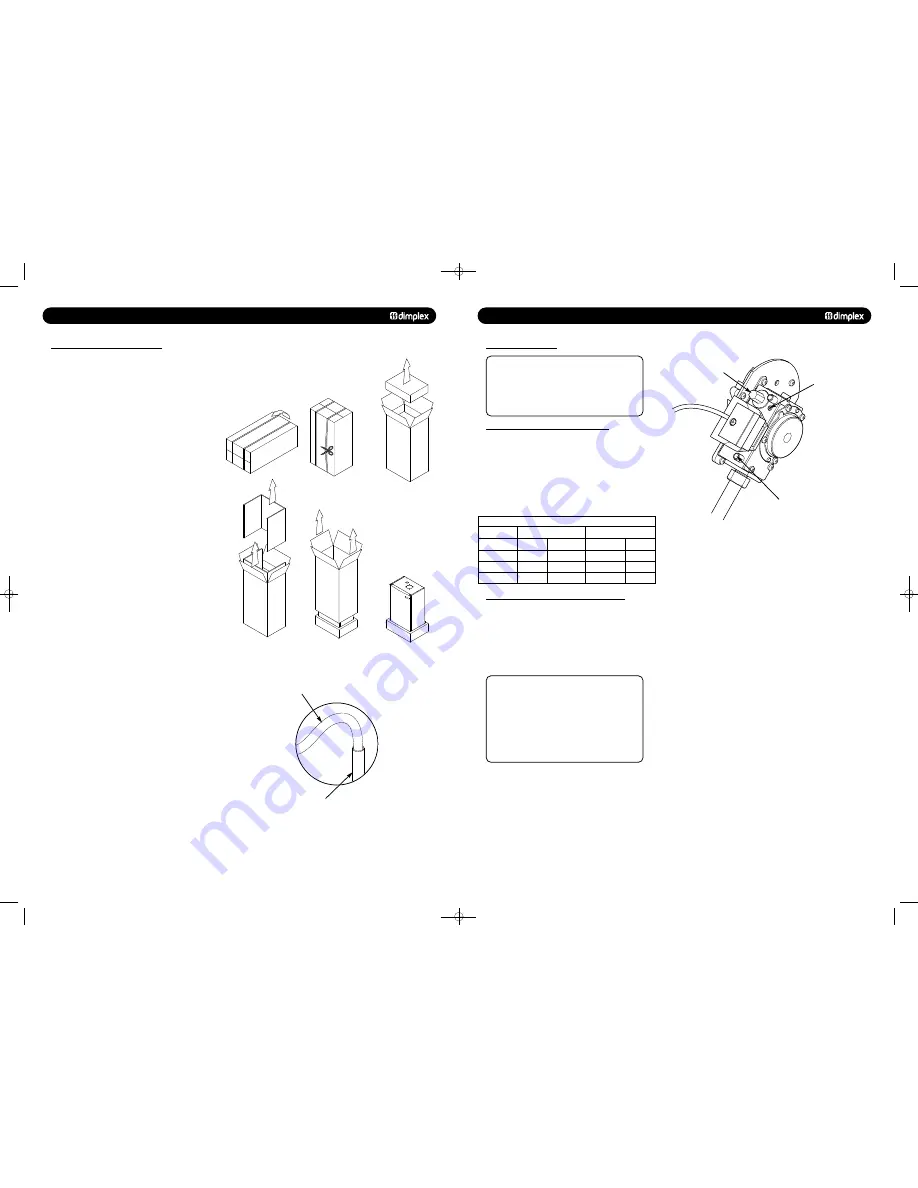
1. Remove the top cardboard tray from the carton.
2. The wall fixing jig is packed in its own cardboard sleeve.
Carefully slide this out of the carton.
3. To avoid scratching the boiler outercase, keep the outer
carton in place.
4. After reviewing the site requirements (see Section 7.0),
position the fixing template on the wall ensuring it is level both
horizontally and vertically.
5. Mark the position of the fixing holes for the wall plate and
boiler lower fixing holes.
6. Mark the position of the centre of the flue hole (rear exit).
For side flue exit, mark as shown (Fig. 4).
7. If required, mark the position of the gas and water pipes.
Remove the template.
8. Cut the hole for the flue (minimum diameter 110mm).
9. Drill the wall as previously marked to accept the wall plugs
supplied. Secure the wall fixing jig using the fixing screws.
10. Using a spirit level ensure that the fixing jig is level before
finally tightening the screws.
11. Flush and clean the system using an appropriate cleanser
(Fig. 30).
12. Connect the gas and water pipes to the valves on the wall
fixing jig.
13. Fit the filling loop as described in the instructions supplied
with it.
22
© Dimplex Boilers 2008
Fig. 30
Flushing Pipe
Central Heating Flow
or Return Pipe
Fig. 29
10.0
COMMISSIONING
10.2
FACTORY SETTINGS
1. With the boiler firing at maximum gas rate, check that the
inlet pressure at the appliance is /- 1mbar when
measured at the inlet pressure test point (Fig. 44).
To set the boiler to maximum gas rate see section
11.0 (Service Mode).
2. Check the maximum and minimum gas rate at the gas meter
according to the table below using a stopwatch.
NOTE: This boiler is supplied factory set for operation on
natural gas. No further adjustments of the air/gas ratio
valve or measurement of the combustion performance are
necessary at the time of installation and commissioning.
This is provided the appliance has been installed according
to these instructions and the inlet gas pressure is within
our specification.
© Dimplex Boilers 2008
27
NOTE: If any doubts exist over the above checks then the
combustion of the appliance can be measured as described
in Section 12.0 of these instructions providing;
• The person carrying out the measurement has been
assessed as competent in the use of a flue gas analyser
and the interpretation of the results.
• The flue gas analyser used, meets the requirements of
BS7927 or BS-EN50379-3.
• The flue gas analyser is calibrated in accordance with the
manufacturers requirements.
10.3
INLET PRESSURE AND GAS RATE CHECKS
1. On completion of the gas inlet pressure and gas rate checks,
it is necessary to check the following:
•
The appliance installation conforms to these instructions.
• The installation and integrity of the full flue system
including the seals in the flue pipes.
•
The boiler combustion circuit, including the burner door
seal, combustion door seal.
2. The recorded combustion values should be compared with
the values in Table 1 and Table 2 (see Section 12.2).
3. If the combustion value(s) is outside the values specified in
Section 12.2 (Tables 1 & 2), do not attempt to adjust the
air/gas ratio valve, please ring the helpline number -
0844 371 1121. If in doubt - ASK.
10.4
COMBUSTION CHECKS DURING COMMISSIONING
Gas Rates (Natural Gas) after 5 minutes from cold
Maximum Rate
Boiler Model
m
3
/h
ft
3
/h
m
3
/h
ft
3
/h
Combi 24
2.6
91.8
0.59
20.8
Combi 30
3.31
116.9
0.73
25.7
Combi 38
4.1
144.7
0.97
34.2
Minimum Rate
Fig. 44
NOTE:
Factory set - warranty
void if adjusted
Throttle Adjuster Screw
Gas Valve
Inlet Test Point
48pp MANUAL SPREADS 19/10/10 08:36 Page 22


