


7. Burner
a. It is easier to lift out the fan cover if you
first remove the oven shelf runners:
(i) Pull the bottom edge away from the
oven side.
(ii) Disengage the runners from the
hanging holes.
b. From the inside of the oven, unscrew
the 4 screws which secure the fan
cover to the back of the oven.
c.
Remove 2 screws from electrode
bracket.
d. Remove rear service panel (5).
e. Prevent motor from rotating whilst
unscrewing burner from within oven.
Note:
Left hand thread, turn clock-
wise to unscrew.
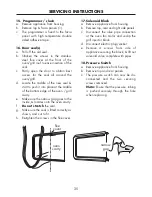
8. Micro-computer
a. Gain access to the rear chamber (5)
and disconnect all wire connectors
from PCB.
b. Remove the PCB earthing screw found
near the spark transformer.
c.
Ensure the distance tube around the
earthing screw is retained and
replaced when refitting the PCB.
d. The complete board can now be
removed by disconnecting the
insulating stand-offs.
Note:
It is practically impossible to
exchange individual components from
the computer board. A complete new
board should be substituted.
9. Cooling fan
a. Remove appliance from housing unit (2).
b. Gain access to rear compartment (5).
c.
Disconnect the fan leads from the
terminal block.
d. Unscrew the 4 screws which secure
the fan mounting bracket.
e. Remove the 4 screws which secure the
fan to the mounting bracket.
10. Door switch
a. Remove appliance from housing unit (2).
b. Remove top panel and RHS panel.
c.
Unscrew the screws which secure the
door switch and its bracket to the oven
door frame.
11. Oven light fitting(s)
a. Remove appliance from housing unit (2).
b. Remove the top and side panels.
c.
Remove the leads from the back of the
light fitting.
d. Squeeze in the metal retaining clips to
release the fitting from the oven side.
12. Grill burner
a. Remove appliance from housing unit (2).
b. Unscrew the top & rear panel securing
screws.
c.
Remove the top & rear panels.
d. Unclip the grill injector holder.
e. Unscrew the grill assembly from the
side struts and lift out the complete
assembly.
13. Ceramic grill glass
a. Gain access to top compartment (5).
b. Remove the grill burner (12).
c.
Lift up all the tabs which secure the
grill glass.
d. Replace the glass & bend the tabs
down.
14. Grill igniter electrode
a. Gain access to the top and rear
compartment (5).
b. Remove the grill burner assembly (12)
and unplug the connecting line at the
control board.
SERVICING INSTRUCTIONS
34
Содержание 900gr
Страница 1: ......


