background image

www.gdts.one

DOK41 HOIAO C0DEN · FD 9912

17

Air-to-water heat pump 9 - 12 kW

English

7 Commissioning

7.1 General

To ensure that commissioning is performed correctly, it should
only be carried out by an after-sales service technician author-
ised by the manufacturer. 

HINWEIS

ºº

º

ºº

º

NOTE

Personal protective equipment (protective goggles, safety
shoes and gloves where necessary) must be used when work-
ing on the device. Components with plastic parts must be pro-
tected  from  impact  (e.g.  from  tools)  to  prevent  damage  to
these components.

7.2 Preparation

The following items must be checked prior to commissioning:

All of the indoor unit connections must be installed.

All of the outdoor unit connections must be installed.

The domestic hot water cylinder must be completely filled
and the domestic hot water feed open.

All valves which could impair the proper flow of the heating
water in the heating circuit must be open.

The air intake and air outlet paths must be clear.

The settings of the master unit must be adapted to the
heating system in accordance with the operating instruc-
tions.

The heating water circuit and the buffer tank must be com-
pletely filled and purged.

Ensure that the condensate drain functions properly.

The outflow from the heating water pressure relief valve
must also function correctly.

The system must be completely filled with refrigerant and
the shut-off devices completely open. 

7.3 Procedure 

The heat pump is commissioned using the master unit or a
smart device paired with the pump. See the “Operation” manual
for instructions on operation, adjustment and set-up.
At heating water temperatures under 7 °C, commissioning is
not possible. The water in the buffer tank must be heated with
the 2nd heat generator to at least 20 °C.
To ensure problem-free commissioning, the following proce-
dure is to be implemented:
1) Close all consumer circuits.
2) Ensure that the heat pump has the correct water flow.
3) Wait until a return temperature of at least 25 °C has been

reached.

4) Now slowly reopen the heating circuit valves in succession

so that the heating water flow rate is constantly raised by
slightly opening the respective heating circuit.   The heat-
ing water temperature in the buffer tank must not be al-
lowed to drop below 20 °C during this process. This en-
sures that the heat pump can be defrosted at any time.

5) When all heating circuits are fully open and a return tem-

perature of at least 20 °C is maintained, the commissioning
is complete. 

!!

ATTENTION!

Operating the heat pump at low system temperatures may
cause the heat pump to break down completely.

Содержание 091HOIAOC6

Страница 1: ...rder no DOK41 HOIAO C0DEN EN FD 9912 System M Comfort 9 12 kW Installation and Operating Instruction Air to Water Heat Pump in Integral Design Glen Dimplex Thermal Solutions Dimplex 091HOIAOC6 121HOIAOC6 ...

Страница 2: ......

Страница 3: ...ensate drain 10 6 3 Connection on heating side 10 6 4 Temperature sensor connection 11 6 5 Electrical connection 12 6 6 Refrigerant pipe connections 15 7 Commissioning 17 7 1 General 17 7 2 Preparation 17 7 3 Procedure 17 8 Cleaning maintenance 18 8 1 Maintenance 18 8 2 Cleaning the indoor unit 18 8 3 Cleaning the outdoor unit 18 9 Faults troubleshooting 19 10 Decommissioning disposal 19 11 Device...

Страница 4: ...This unit can be used by children aged 8 and over and by per sons with limited physical sensory or mental aptitude or lack of experience and or knowledge providing they are supervised or have been instructed in the safe use of the unit and understand the associated potential dangers Children must not play with the device Cleaning and user maintenance must not be carried out by children without su ...

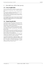
Страница 5: ...he air i e ex tracts heat from it This extracted heat is then transferred to the working medium refrigerant in the evaporator The heat is pumped to a higher temperature level by increas ing its pressure with the aid of the electrically driven compres sors It is then transferred to the heating water via the liquefier heat exchanger Electrical energy is used to raise the temperature level of the hea...

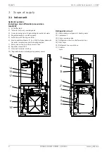
Страница 6: ...x with heating controller 6 Electric additional heater 2 4 or 6 kW for higher domestic hot water temperatures and for heating support 7 Safety valve start to leak pressure 2 5 bar 8 Expansion vessel 24 l 9 Universal hardware interface 10 Regulated heat circulating pump primary circuit Refrigeration circuit 11 Heat exchanger refrigerant heating water 12 Compressor 13 4 way reversing valve 14 Refrig...

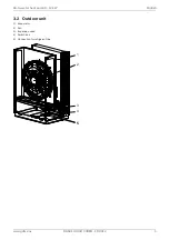
Страница 7: ...www gdts one DOK41 HOIAO C0DEN FD 9912 5 Air to water heat pump 9 12 kW English 3 2 Outdoor unit 1 Evaporator 2 Fan 3 Expansion valve 4 Switch box 5 Connection for refrigerant line 1 2 4 3 5 5 ...

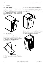
Страница 8: ... directly underneath the pallet To lift from the pallet the indoor unit can be tilted back by up to 45 and lifted by the handles on the back at the top Tilting more than 45 is not permitted Once the two side sections have been removed the device also has the option of inserting support tubes through the holes in the frame The casing panels must be dismantled in the order outlined be low The right ...

Страница 9: ...to water heat pump 9 12 kW English After the final positioning at the installation location remove the transport fastening on the sprung floor of the compressor on both sides ATTENTION Before commissioning the transport fastening must be re moved ...

Страница 10: ...tallation lies with the specialist system construction company During the installation local requirements such as building reg ulations static load of the building and wind exposure must be accounted for ad of the building and wind exposure must be accounted for It must be possible to carry out maintenance work without hin drance This is ensured if the clearance displayed below is maintained The s...

Страница 11: ...her frost nor temperatures higher than 35 C must occur in the installation location at any time of the year The minimum volume of the room where the heat pump is in stalled must be no less than the following value depending on the refrigerant quantity in the device If the refrigerant quantity is increased the room volume must be calculated according to the following formula minimum permissible roo...

Страница 12: ...or unit parallel to the noz zle ring heater E4 ATTENTION The frost line can vary according to the climatic region The regulations of the countries in question must be observed 6 3 Connection on heating side Before connecting the heating system to the heat pump the heating system must be flushed to remove any impurities resi due from sealants etc Any accumulation of deposits in the liq uefier may c...

Страница 13: ...flow rate Frost protection A method of manual drainage should be provided for heat pumps which are exposed to frost The frost protection func tion of the heat pump manager is active whenever the heat pump manager and the heat circulating pump are ready for op eration The system must be drained if the heat pump is taken out of service or in the event of a power failure The heating cir cuit should b...

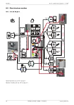
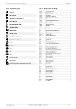
Страница 14: ...OK41 HOIAO C0DEN FD 9912 www gdts one English Air to water heat pump 9 12 kW 6 5 Electrical connection 6 5 1 Circuit diagram Symbol legend see cap 6 5 2 on page 13 Equipment marking see cap 6 5 3 on page 13 ...

Страница 15: ...ater A441 Bivalent A442 Renewable A451 Cooling active B3 domestic hot water thermostat B4 Swimming pool water thermostat E10 1 Electrical heater E10 2 3 Oil gas boiler H5 Remote fault indicator K21 Flange heater K22 Utility block K23 Disable contactor K28 Switching heating cooling K31 Circulation system requirements M13 Heat pump heating circuit 1 M15 Heat pump heating circuit 2 M16 Auxiliary circ...

Страница 16: ... N PE 230 V 50 Hz must have a continuous voltage For this reason it should be tapped upstream from the utility blocking con tactor or be connected to the household current because otherwise important protection functions could be lost during a utility block Utility block The utility blocking contactor K22 with 3 main contacts 1 3 5 2 4 6 and an auxiliary contact NO contact 13 14 should be dimensio...

Страница 17: ... 2 Pipe connection The connection points for the refrigerant lines must be estab lished using the brazing process All generally applicable instal lation and work steps must be followed for this During the brazing process the pipe system must be flushed with an inert gas e g nitrogen The adjacent components must be suitably cooled to prevent them being damaged 6 6 3 Leak test and evacuation Air and...

Страница 18: ...d An absolute pressure of at least 0 2 mbar must be achieved during evacuation Pressures below 0 2 mbar are advisable however Close the vacuum pump and start filling immediately Step 4 Filling Once the leakage tightness test and evacuation have been car ried out correctly open the maintenance valves on the indoor unit For refrigerant lines 7 0 m top up the refrigerant accord ingly The heat pump is...

Страница 19: ...e condensate drain functions properly The outflow from the heating water pressure relief valve must also function correctly The system must be completely filled with refrigerant and the shut off devices completely open 7 3 Procedure The heat pump is commissioned using the master unit or a smart device paired with the pump See the Operation manual for instructions on operation adjustment and set up...

Страница 20: ...end equipping dif fusion open heating systems with an electrophysical corro sion protection system e g ELYSATOR system Residue from lubricants and sealants may also contaminate the heating water In the event of severe contamination leading to a reduction in the performance of the liquefier in the heat pump the system must be cleaned by a heating technician Based on current information we recommend...

Страница 21: ...the power supply HINWEIS º º º º º º NOTE Personal protective equipment protective goggles safety shoes and gloves where necessary must be used when work ing on the device Components with plastic parts must be pro tected from impact e g from tools to prevent damage to these components 10 Decommissioning disposal Before removing the heat pump disconnect the machine from the power source and close a...

Страница 22: ...n accordance with EN 12102 at A7 W55 indoors dB A 45 45 3 6 Sound pressure level at a distance of 1 m indoors4 dB A 34 34 3 7 Air flow Normal operation reduced operation3 m h 3300 2900 3800 3000 4 Dimensions weight and filling quantity 4 1 Device dimensions5 indoors without connections H x W x L mm 1400 x 600 x 750 1400 x 600 x 750 outdoors without connections H x W x L mm 1230 x 850 x 600 1230 x ...

Страница 23: ... achieved with clean heat exchangers Information on maintenance commissioning and operation can be found in the respective sections of the installation and operating instructions The specified values e g A2 W35 have the following meaning outside air temperature 2 C and heating water flow temperature 35 C 3 The heat output and COP is reduced by approx 5 in lower operation 4 The specified sound pres...

Страница 24: ... 0 5 m 0 5 m Direction of air flow Minimum clearances 460 39 710 40 790 Hatched area footprint 850 1231 600 206 790 538 695 995 95 55 105 40 538 39 4x Ø17 5 Fixing holes base frame for M12 27 110 40 205 108 Foundation Drain pipe Ø50 mm flush with foundation Condensate hose 160 30 30 1 1 1 2 1 4 1 3 1 5 1 3 1 3 1 1 1 2 1 1 1 2 1 6 1 7 4 0 0 174 120 50 866 608 1 8 1 8 1 9 ...

Страница 25: ...C0DEN FD 9912 23 Air to water heat pump 9 12 kW English 12 2 Dimension drawing indoor unit 2 8 2 9 2 1 2 10 2 3 2 2 2 7 2 12 2 11 600 1400 544 722 750 113 125 95 0 117 187 490 560 840 910 980 1050 1120 1190 60 ca 60 ca 95 2 14 ...

Страница 26: ...eedthrough electric wires 12 mm 1 7 Optional feedthrough electric wire 1 8 External dimensions wood design variant 1 9 MPRO16 accessory set for optional rear connection of the refrigerant lines 2 Indoor unit 2 1 Outlet overpressure 2 2 Feed through electric wire indoor unit 2 3 Feed through refrigerant line indoor unit 2 7 Flow heating G 1 1 4 2 8 Return heating G 1 1 4 2 9 Flow domestic hot water...

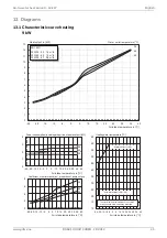
Страница 27: ... m h 0 2 4 6 8 25 20 15 10 5 0 5 10 15 20 25 30 35 40 Air intake temperature in C Coefficient of performance incl proportion of pump output 35 45 55 0 1 2 3 4 25 20 15 10 5 0 5 10 15 20 25 30 35 40 Air intake temperature in C Power consumption including proportion of pump output kW 55 45 35 10 15 20 25 30 35 40 45 50 55 60 65 25 20 15 10 5 0 5 10 15 20 25 30 35 40 Air intake temperature in C Heati...

Страница 28: ... 4 5 25 20 15 10 5 0 5 10 15 20 25 30 35 40 Air intake temperature in C Power consumption including proportion of pump output kW 55 45 35 10 15 20 25 30 35 40 45 50 55 60 65 25 20 15 10 5 0 5 10 15 20 25 30 35 40 Air intake temperature in C Heating water temperature C The maximum ÀRw temperatures are achieved Water outlet 2K min water inlet 2K 0K 0 1 2 3 4 5 6 7 8 9 10 11 12 13 14 15 16 17 25 20 1...

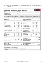
Страница 29: ... Emissions of nitrogen oxides NOx mg kWh Declared load profile Water heating energy efficiency ηwh Daily electricity consumption Qelec kWh Daily fuel consumption Qfuel kWh Contact details If Cdh is not determined by measurement nthen the default degradation is Cdh 0 9 not applicable For air to water heat pumps Rated air flow rate outdoors For water brine to water heat pumps Rated brine or water fl...

Страница 30: ... kWh Declared load profile Water heating energy efficiency ηwh Daily electricity consumption Qelec kWh Daily fuel consumption Qfuel kWh Contact details If Cdh is not determined by measurement nthen the default degradation is Cdh 0 9 not applicable For air to water heat pumps Rated air flow rate outdoors For water brine to water heat pumps Rated brine or water flow rate outdoor heat exchanger Decla...

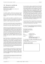
Страница 31: ... covered by the warranty If it was not possible to remedy the defect the manufacturer shall either deliver a replacement free of charge or issue a reimburse ment for the reduced value In cases in which replacement is pro vided we reserve the right to apply a reasonable utilisation charge for the period of usage elapsed to date Additional or further claims in particular regarding compensation for d...

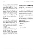
Страница 32: ...rt en cryption methods III Use of service providers Personal data required for maintenance purposes such as your address contact details and framework data on the contract is made available to after sales service partners so that they can carry out maintenance and repair services The control and operating data is evaluated and analysed by a service provider however this service provider only recei...

Страница 33: ...www gdts one DOK41 HOIAO C0DEN FD 9912 31 Air to water heat pump 9 12 kW English 17 Declaration of conformity You can find and download the current CE conformity declaration at https gdts one m ...

Страница 34: ...32 DOK41 HOIAO C0DEN FD 9912 www gdts one English Air to water heat pump 9 12 kW ...

Страница 35: ...www gdts one DOK41 HOIAO C0DEN FD 9912 33 Air to water heat pump 9 12 kW English ...

Страница 36: ...39 dimplex gdts one www gdts one Geschäftsstelle Österreich Glen Dimplex Austria GmbH Hauptstraße 71 A 5302 Henndorf am Wallersee T 43 6214 20330 F 43 6214 203304 info dimplex at www dimplex at Office France Dimplex SAS 7 rue d Uberach 67590 Schweighouse Sur Moder T 33 3 88 07 18 00 F 33 3 88 07 18 01 dimplex ST dimplex de www dimplex de fr ...

Отзывы: