


16
DOK41 HOIAO WxDEN · FD 9912
www.gdts.one
English
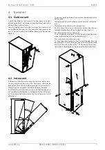
Air-to-water heat pump 4 - 6 kW
6.6.4 Electrical connection general
All connection cables must be provided on-site. The cable type
(cross-section, conductor type, etc.) must be chosen taking
into account the relevant electrical parameters (e.g. power, cur-
rent, voltage, etc.) and the applicable VDE, EN and VNB regula-
tions. Information on this can be found in the device informa-
tion and the electrical documentation as a planning aid.
!!
ATTENTION!
The plugs are protected against being pulled. They must be
released with a small screwdriver before disconnecting.
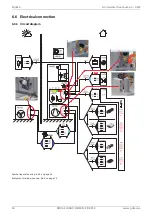
6.6.5 Electrical connection indoor unit
For operating the heat pump, at least the following cables / sig-
nals must be connected:
Supply voltage / refrigeration circuit
An all-pole disconnecting device with a contact gap of at
least 3 mm (e.g. utility blocking contactor or power contac-
tor) must be installed in the refrigeration circuit power sup-
ply. A 3-pole circuit breaker with joint tripping of all outer
conductors (trip current in accordance with device infor-
mation) provides the short circuit protection taking into ac-
count the layout of the internal wiring. The relevant com-
ponents in the heat pump contain an internal overload
protection.
For connecting on the switch box of the refrigeration cir-
cuit on +A100-X1, check for the clockwise rotating field of
the load feed.
Phase sequence: L1, L2, L3.
!!
ATTENTION!
Ensure the rotary field is clockwise when connecting the
mains cables (if the rotary field is not clockwise, the heat
pump will not work properly, is very loud and may cause dam-
age to the compressor).
Communication / control voltage (hydraulics <-> refrigera-
tion circuit)
The communication and control voltage cable from the hy-
draulic switch box (with heat pump manager) to the refrig-
eration circuit are already pre-wired and end on the plugs
+A100-X2 (control voltage) and +A100-X5.1 (communica-
tion). These may still have to be inserted
Control voltage
The three-core supply cable for the heat pump manager
(+A200-N1) is fed into the heat pump to the hydraulic
switch box +A200-X2. The supply cable (L/N/PE ~230 V,
50 Hz) must have a continuous voltage (+A300). For this
reason, it should be tapped upstream from the utility
blocking contactor or be connected to the household cur-
rent, because otherwise important protection functions
could be lost during a utility block.
Utility block
The utility blocking contactor (K22) with 3 main contacts
(1/3/5 // 2/4/6) and an auxiliary contact (NO contact 13/
14) should be dimensioned according to the heat pump
output and must be supplied on-site. The potential-free
NO contact of the utility blocking contactor (13/14) is
wired to the hydraulic switch box and must be connected
on the plug +A200-XK22 there.
Caution! Extra-low volt-
age!
External sensor
The external sensor is connected to the hydraulic switch
box via the +A200-XR1 plug
Supply voltage hydraulics
For the power supply to the 2nd heat generator, a wire
must be routed to the device according to the power (2,4,6
kW configurable) and connected to the hydraulic switch
box on plug +A400-X1.
In delivery state, the 2nd heat generator is configured to
6kW to guarantee that the increased heat consumption is
met while drying out the building. In regular operation, this
must be adapted to the actual required additional heating
output (integrated system label).
To reduce it to 4 or 2 kW, one or two connections between
+A400-K20 (relay 2nd heat generator) and +A400-F17
(safety temperature limiter)- both located in the hydraulic
switch box - must be removed.
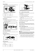
6.6.6 Electrical connection outdoor unit
A power supply (plug +A110-X1 <-> +A100-XA110) and com-
munication line (plug +A110-X5 <-> +A100-X5.2) must be
routed parallel to the refrigerant line between the refrigeration
circuit and the outdoor unit.
HINWEIS
ºº
º
ºº
º
NOTE
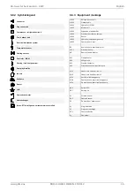
The assignment of the heat pump manager is system-de-
pendent and outlined in the Quick Installation Guide. The
functions on the heat pump manager are also documented on
a system-dependent basis.
6.6.7 LAN / network connection
The heat pump is only designed for connection to the internet
via a router. This ensures that the user can access the system at
any time for setting parameters or for reading out information.
Maintenance work or software updates are much easier.
A conventional network cable (Cat. 5) is required for connec-
tion, which is connected between an external router (+A350)
and the network interface (+A210) of the indoor unit.
Содержание 041HOIAOW2
Страница 2: ......
Страница 37: ...www gdts one DOK41 HOIAO WxDEN FD 9912 35 Air to water heat pump 4 6 kW English...
Страница 38: ...36 DOK41 HOIAO WxDEN FD 9912 www gdts one English Air to water heat pump 4 6 kW...
Страница 39: ...www gdts one DOK41 HOIAO WxDEN FD 9912 37 Air to water heat pump 4 6 kW English...