Gilson Company, Inc.
Micro-Deval Apparatus: MD-2000, MD-2000C & MD-2000F
Page 7
• Close the doors properly to insure the safety interlock
is active and press the Green <START> button. The
jars will turn and the controller will count down to zero
while the revolutions counter counts up to the setpoint.
Power to the motor will then cut off.
7.0 OPERATING INSTRUCTIONS:
The MD-2000 is now ready to perform a test.
For additional tests with the same time or number of
revolutions, simply press the green <START> button.
NOTE: The counter will retain the last number
displayed if power is interrupted. The instrument
can resume a test after a power outage by pressing
the green <START> button.
7.1 Performing a Test:
To perform a test with the MD-2000, first refer to the test
protocol in the governing specifications and prepare the
aggregate specimen as specified.
1. Load the prepared sample into the abrasion jar
along with the specified amounts of abrasive charge
(stainless steel balls) and water.
2. Carefully clean and dry off the rim of the jar and the
lid gasket.
3. Place the lid on the jar and secure with the threaded
locking knob.
NOTE: Excessive tightening of the knob may result
in deformation of components. Tighten only until
snug and free from leaks.
4. Invert the jar and check for leaks.
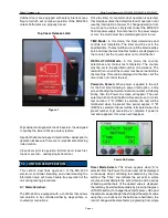
5. Place the jar on its side on the roller set with the clamping
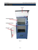
end facing the optical encoder (see Figure 4).
6. Check that timer or revolutions mode is selected
properly and that settings are correct. If necessary,
input new settings as noted in previous section.
7. Check that there are no foreign objects or obstructions
in the jar chambers.
8. Close and secure the cabinet doors; first the bottom
then the top, latching door.
9. Press the green <START> button. Depending on the
mode selected, the timer or the revolutions counter
will then control the duration of the test and stop the
machine automatically at completion.
NOTE: Pressing the large, red <STOP> button
located on the front panel will cut power to the
motor and rotation will cease. Pressing the green
<START> button will resume operation.
WARNING!
It is possible for pressure to build inside the sealed
jars during testing. Use caution when removing the
jar lid after completion of test.
8.0 MAINTENANCE:
WARNING!
Always disconnect and lockout the power supply to
this machine before performing any maintenance
or repair.
No normal maintenance procedures require access to
the cabinet interior. There are no lubrication points on
the instrument.
Upper Level
Optical Encoder Sensor
Figure 4
Lower Level
Optical Encoder Sensor

