background image

er or Authorised Service Centre

 in order to carry out a thorough inspection of the

braking system.

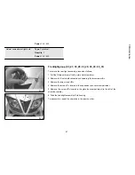
03_19

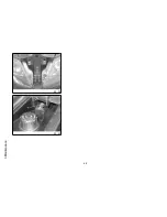
03_20

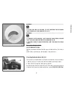
Brakingsystemfluidtopup (03_19, 03_20)

Proceed as follows: Unscrew the two screws «

B

», remove the fuel tank cap and the

intermediate rubber membrane, and top-up the brake fluid level using only the rec-
ommend brake fluid type and without exceeding the maximum level.

Under normal climatic conditions, the brake fluid must be replaced every 20,000 km
or every two years, whichever comes first. This operation must be carried out by
trained technicians, please contact your nearest 

Piaggio-Gilera Dealer or Author-

ised Service Centre

.

WARNING

ONLY USE DOT 4-CLASSIFIED BRAKE FLUID. BRAKE CIRCUIT FLUID IS VERY
CORROSIVE; MAKE SURE THAT IT DOES NOT COME INTO CONTACT WITH
THE PAINTWORK.

CAUTION

AVOID CONTACT OF BRAKE FLUID WITH EYES, SKIN, AND CLOTHING. IN
CASE OF CONTACT, RINSE WITH WATER. THE BRAKING CIRCUIT FLUID IS
HYGROSCOPIC, THAT IS, IT ABSORBS HUMIDITY FROM THE SURROUNDING
AIR. IF THE HUMIDITY IN THE BRAKING FLUID EXCEEDS A CERTAIN VALUE,
IT WILL LEAD TO INEFFICIENT BRAKING. NEVER USE BRAKING FLUID KEPT
IN CONTAINERS THAT HAVE ALREADY BEEN OPENED, OR PARTIALLY USED.

Recommended products

AGIP BRAKE 4

Brake fluid.

58

3 Maintenance

Содержание Nexus 250 i.e.

Страница 1: ...mation tips and precautions for using your vehicle It also describes features details and devices to assure you that you have made the right choice We believe that if you follow our suggestions you will soon get to know your new scooter and it will serve you well for a long time to come This booklet forms an integral part of the vehicle should the vehicle be sold it must be transferred to the new ...

Страница 2: ...regular checks that should be carried out on the vehicle at an authorised Dealer or Service Centre The booklet also contains instructions for simple repairs Any operations not specifically described in this booklet require the use of special tools and or particular technical knowledge to carry out these operations refer to any authorised Dealer or Service Centres 2 ...

Страница 3: ...ging the environment Vehicle intactness The incomplete or non observance of these regulations leads to the risk of serious damage to the vehicle and sometimes even the invalidity of the guarantee The signs that you see on this page are very important They are used to highlight parts of the booklet that should be read with particular care The different symbols are used to make each topic in the man...

Страница 4: ...4 ...

Страница 5: ...28 USE 31 Checks 32 Refuelling 32 Tyrepressure 34 Shockabsorbersadjustment 35 Runningin 36 Startinguptheengine 37 Precautions 39 Difficultstartup 39 Stoppingtheengine 40 Stand 40 Automatictransmission 41 Safedriving 42 MAINTENANCE 45 Engineoillevel 46 Engineoillevelcheck 46 Engineoiltop up 47 Warninglight insufficientoilpressure 48 Engineoilchange 48 Huboillevel 49 Tyres 51 Sparkplugdismantlement ...

Страница 6: ... Rear viewmirrors 73 Frontandreardiscbrake 74 Puncture 75 delveicolo 76 Cleaningthevehicle 76 TECHNICALDATA 81 Toolkit 85 SPAREPARTSANDACCESSORIES 87 Warnings 88 SCHEDULEDMAINTENANCE 91 Scheduledservicingtable 92 6 ...

Страница 7: ...Nexus 250 i e Chap 01 Vehicle 7 ...

Страница 8: ...01_01 8 1 Vehicle ...

Страница 9: ...brake lever E Digital instrument panel F Turn signal switch G Light switch H Combined braking system control front and rear I Horn button L Emergency cut off switch M Free position N Warning light unit O Analogue instrument panel P Warning light unit on digital instrument panel 9 1 Vehicle ...

Страница 10: ...Q Remote Mode switch R Passing 01_03 10 1 Vehicle ...

Страница 11: ...trol warning light and injection system failure warning light D Low fuel warning light M Low oil pressure warning light F Turn indicator warning light G Antitheft device LED H LCD Display I Odo Set button L Clock button M Mode button Q Remote Mode button See Engine stop section 11 1 Vehicle ...

Страница 12: ...Indicatorunir 01_05 A Warning light preinstallation B Headlight warning light C High beam warning light D Warning light preinstallation 01_05 12 1 Vehicle ...

Страница 13: ...the hours will begin flashing Set the hours with the ODO SET button Push the CLOCK button again and the minutes numbers start flashing Set the minutes with the ODO SET button Press the CLOCK button again to start the clock moving normally During the reset process not pressing any buttons for a period longer than 8 seconds ends the process automatically and the display shows the modified time 01_07...

Страница 14: ...iles gallons icon E Fuel gauge F 3 digit display G Miles per hour icon H Total odometer indicator I Partial odometer indicator L Km h Km l indicator M 5 digit display N Fuel consumption and autonomy gauge O Maximum speed indicator P Mean speed consumption Q Water temperature gauge 14 1 Vehicle ...

Страница 15: ...ecked or replaced In any case vehicle maintenance must be carried out at the service intervals recom mended in the Scheduled Maintenance WARNING REFER TO THE SCHEDULED MAINTENANCE TABLE FOR FURTHER MAIN TENANCE OPERATIONS Settingthetotalandtripodometers Pressing the ODO SET button the display shifts from total to partial odometer Hold ODO SET button down longer than 3 seconds to reset the partial ...

Страница 16: ...e year with the ODO SET button Push the CLOCK button again and the month numbers start flashing Set the month with the ODO SET button Push the CLOCK button again and the day numbers start flashing Set the day with the ODO SET button CAUTION IT IS STRONGLY ADVISED NOT TO USE THE FUNCTIONS OF THE DIGITAL DISPLAY PANEL WHILE THE VEHICLE IS MOVING 16 1 Vehicle ...

Страница 17: ...ayed 5 AUTONOMY The fuel icon is displayed If autonomy is reduced below 40 km this icon is automatically displayed and flashes for 60 seconds If the low fuel warning light remains continuously lit some dashes are shown instead of the autonomy value 6 BATTERY VOLTAGE The battery icon is displayed Should voltage be ab normal the icon is displayed and flashes for 60 seconds Pushing the MODE button lo...

Страница 18: ...sa bled 3 ON Ready to start non extractable key mechanical antitheft device disa bled 4 SADDLE OPENING Saddle opening position Push the key in position and turn it counterclockwise Lockingthesteeringwheel Turn the handlebar to the left as far as it will go turn the key to LOCK and remove the key Releasingthesteeringwheel Reinsert the key and turn it to OFF 18 1 Vehicle ...

Страница 19: ..._12 Lever towards S Left turn indicator is switched on Lever towards D Right turn indicator is switched on The lever returns automatically to position 0 and the turn indicator B remains on to switch off push the lever again 01_13 Hornbutton 01_13 Push the C button to sound the horn 19 1 Vehicle ...

Страница 20: ...01_14 01_15 Lightswitch 01_14 01_15 Light switch A 0 Low beam light 1 High beam light E Passing flash 01_16 Start upbutton 01_16 Start up button C 20 1 Vehicle ...

Страница 21: ... OFF to ON If the warning light remains fixedly on after the check period or lights up under normal use conditions take your vehicle to an Authorised Piaggio Gilera Service Centre to solve the problem Theimmobilizersystem In order to enhance theft protection the vehicle is equipped with a PIAGGIO IMMO BILIZER electronic engine locking device that is activated automatically when the ignition switch...

Страница 22: ...herefore recommend that it be used only under exceptional circumstances The black key B single copy supplied is used for normal operations such as engine start up unlocking the fuel tank cover Together with the two keys you will be given a CODE CARD bearing the mechanical code of the keys WARNING LOOSING THE RED KEY PREVENTS ANY REPAIRS OF THE PIAGGIO IMMO BILIZER SYSTEM AND THE ENGINE CONTROL UNI...

Страница 23: ...irst to OFF and then to ON if the lock cannot be disabled try with the other key supplied red coloured If it is still not possible to start the engine it is absolutely necessary to turn to an Authorised Piaggio Gilera Service Centre that has the equipment necessary for diagnosis and repair of the system The immo bilizer is also activated when the engine cut off switch stops the engine or the side ...

Страница 24: ... handgrip key into the switch key in OFF and turn it to ON After 1 3 seconds turn the key to OFF again and pull it out Intermediatestep blackkey After pulling out the red key insert the black key within 10 seconds and promptly turn it to ON After 1 3 seconds turn the key to OFF again and pull it out In this way a maximum of 7 black keys can be programmed by repeating the above procedure keeping th...

Страница 25: ...EY WITH TRANSPONDER OFF OR IN THE EVENT OF WRONG OPERATION DURING PROGRAMMING REPEAT THE PROCEDURE FROM THE BEGINNING 01_23 01_24 Accessingthefueltank 01_23 01_24 To remove the fuel tank cover A lift tab B and insert the key in lock C 25 1 Vehicle ...

Страница 26: ... PROLONGED USE OF THE PLUG SOCKET MAY RESULT IN PARTIAL DIS CHARGE OF THE BATTERY Electric characteristic Plug socket 12 V 180 W MAX Maximum power 180 W 01_26 Thesaddle 01_26 01_27 To lift the saddle and get access to the helmet compartment insert the key in the key switch A With the key set to OFF push it and turn it anticlockwise to the SAD DLE OPENING position 26 1 Vehicle ...

Страница 27: ...he identification registration numbers consist of a prefix stamped on the chassis and engine B followed by a number These numbers must always be indicated on spare parts requests To read the chassis number remove the relevant port A in the helmet compartment We recommend checking that the chassis registration number stamped on the scooter corresponds with that on the scooter s documents CAUTION PL...

Страница 28: ...e rider s needs Unscrew the 3 screws A remove the windshield upper part and set it in the desired position Tighten the 3 fixing screws again WARNING CARRY OUT THIS OPERATION WITH EXTREME CARE SO AS NOT TO SCRATCH THE WINDSHIELD PREVENT WINDSHIELD DETACHMENT WHILE RIDING BY TIGHTENING THE FIXING SCREWS WELL 28 1 Vehicle ...

Страница 29: ...01_31 29 1 Vehicle ...

Страница 30: ...30 1 Vehicle ...

Страница 31: ...Nexus 250 i e Chap 02 Use 31 ...

Страница 32: ... functioning of the front brakes and the combined system 6 The oil level in the gearcase 7 The engine oil level 8 The coolant level 02_01 Refuelling 02_01 02_02 Fuel Remove the tank cover A Recommended fuel Minimum 95 octane unleaded gasoline Fuel level is indicated on the digital instrument panel B WARNING SWITCH OFF THE ENGINE BEFORE REFUELLING WITH PETROL PETROL IS HIGHLY INFLAMMABLE DO NOT SMO...

Страница 33: ...THE CATALYTIC CONVERTER CAUTION USING NON RECOMMENDED PETROL REDUCES THE EFFICIENCY OF THE EXHAUST AND FUEL SUPPLY SYSTEMS CAUTION DO NOT USE THE VEHICLE TO THE COMPLETE EXHAUSTION OF THE FUEL SHOULD THIS OCCUR DO NOT ATTEMPT TO START THE ENGINE TURN THE IGNITION SWITCH TO OFF AND TOP UP THE TANK AS SOON AS POSSIBLE FAILURE TO FOLLOW THESE GUIDELINES COULD DAMAGE THE FUEL PUMP AND OR THE CATALYTIC...

Страница 34: ...ox Fuel tank capacity 14 5 l approx 02_03 Tyrepressure 02_03 Check periodically about every 500 km the pressure and wear of the tyres The tyres are equipped with wear indicators according to which the tyres should be changed before these indicators come to the surface of the tread Check also that the tyres do not have tears on their sides or an irregular pattern of wear on the tread if this occurs...

Страница 35: ...essure 2 3 bar with passenger 02_04 Shockabsorbersadjustment 02_04 The preloading of the springs can be adjusted to 4 positions acting on the ring nut located in the lower part of the shock absorbers with the specific spanner supplied Position 1 minimum preload rider only Position 2 medium preloading rider only Position 3 medium preloading rider and passenger Position 4 maximum preloading rider pa...

Страница 36: ...HIS OPERA TION IN ORDER TO AVOID INJURIES WARNING IT IS ABSOLUTELY FORBIDDEN TO ADJUST THE PRELOAD DIFFERENTLY ON THE TWO SHOCK ABSORBERS 02_05 Runningin 02_05 WARNING DURING THE FIRST 1000 KM DO NOT RIDE THE VEHICLE OVER 80 OF ITS MAXIMUM SPEED AVOID TWISTING THE THROTTLE GRIP FULLY OR KEEP ING A CONSTANT SPEED ALONG LONG SECTIONS OF ROAD AFTER THE FIRST 1000 KM GRADUALLY INCREASE SPEED UNTIL REA...

Страница 37: ...g the starter button E it is necessary to pull and hold pulled the front brake lever G or the combined brake lever D to actuate the safety switches The fuel supply system can control ignition based on the engine condition hot cold or the ambient temperature and pressure 1 Put the scooter on the centre stand F making sure the rear wheel is raised from the ground 2 Keep the throttle grip C completel...

Страница 38: ...OXIC CAUTION DUE TO THE HIGH TEMPERATURES THE CATALYTIC CONVERTER CAN REACH ALWAYS TAKE CARE WHEN PARKING THE VEHICLE THAT THE EX HAUST DOES NOT COME INTO CONTACT WITH FLAMMABLE MATERIALS TO AVOID SERIOUS BURNS CAUTION DO NOT SHUT OFF THE ENGINE WHILE THE VEHICLE IS MOVING UNBURNED FUEL COULD ENTER THE CATALYTIC CONVERTER AND BURN CAUSING THE CONVERTER TO OVERHEAT AND POSSIBLY DESTROYING IT 38 2 U...

Страница 39: ...RNING AFTER A LONG DISTANCE COVERED AT THE MAXIMUM SPEED DO NOT STOP THE ENGINE IMMEDIATELY BUT LET IT RUN AT IDLE FOR A FEW SECONDS WARNING TAMPERING MAY CAUSE SERIOUS ENGINE MALFUNCTION Difficultstartup In the rare case of flooding the engine to facilitate start up it is possible to try to put the scooter into action with the gas hand grip partially or completely open It is however necessary onc...

Страница 40: ...ntwist the throttle grip then rotate the key in the switch A to KEY OFF extractable key 02_10 Stand 02_10 CENTRE STAND Push with your foot on the centre stand s fork F while lifting the vehicle backward holding onto the handlebar 40 2 Use ...

Страница 41: ...uphill If you have to stop up a hill traffic lights traffic jam etc use only the brake to keep the vehicle still leaving the engine running at idle speed Using the engine to keep the vehicle still can cause the clutch to overheat due to the friction of the clutch mechanism itself against the capstan It is therefore recommended to avoid conditions of prolonged clutch slippage other than those previ...

Страница 42: ...lippery roads 5 Avoid riding off by mounting the scooter when it is resting on its support In any case in order to avoid abrupt departures the rear wheel should not be turning when in comes into contact with the ground 6 If you use the scooter on roads covered with sand mud snow mixed with salt etc we recommend that you clean the brake disc frequently with a non aggressive deter gent in order to a...

Страница 43: ...NOT IN A GENERALLY GOOD CONDITION OR WHENEVER WEATHER CONDITIONS DEMAND IT SPEED SHOULD BE FURTHER REDUCED CAUTION DO NOT ADJUST THE MIRRORS WHILE RIDING THIS COULD CAUSE YOU TO LOOSE CONTROL OF THE VEHICLE CAUTION ANY ELABORATION THAT MODIFIES THE VEHICLE S PERFORMANCES SUCH AS TAMPERING WITH ORIGINAL STRUCTURAL PARTS IS STRICTLY FORBID DEN BY LAW AND RENDERS THE VEHICLE NO LONGER CONFORMING TO T...

Страница 44: ...44 2 Use ...

Страница 45: ...Nexus 250 i e Chap 03 Maintenance 45 ...

Страница 46: ...table or before setting off on long journeys The scooter is however equipped with an oil pressure warn ing light on the instrument panel 03_01 Engineoillevelcheck 03_01 03_02 This operation must be carried out with the engine cold and following the procedure below 1 Rest the scooter on the central stand and on a flat ground 2 Set the strut that regulates the position to its minimum height 3 Screw ...

Страница 47: ...el check by adding oil but never exceeding the MAX level The topping up of the level between MIN and MAX requires approx 200 cc of oil Every 5000 km however the engine oil level should be checked and topped up if necessary at an Authorised Piaggio Service Centre 03_03 47 3 Maintenance ...

Страница 48: ...re The engine should be emptied by draining the oil from the drainage cap B of the gauze filter on the flywheel side In order to facilitate the oil drainage loosen the cap dipstick Since a certain quantity of oil re mains in the circuit still the top up should be carried out with around 600 650 cc of oil from cap A Then start up the scooter leave it running for a few minutes and switch it off afte...

Страница 49: ...MA MA2 API SL ACEA A3 03_06 Huboillevel 03_06 03_07 03_08 Check the oil in the rear hub oil content 250 cc To check the rear hub oil level proceed as follows 1 Rest the vehicle onto its centre stand on level ground 2 Unscrew the dipstick A dry it with a clean cloth and then reinsert it screwing it fully into place 3 Pull out the dipstick to control that the oil level reaches the second notch from ...

Страница 50: ...INATED OR IMPROPER LUBRICANTS ACCELERATES THE WEAR AND TEAR OF THE MOVING PARTS AND CAN CAUSE SERIOUS DAMAGE CAUTION USED OIL CAN HARM THE ENVIRONMENT COLLECTION AND DISPOSAL SHOULD BE CARRIED OUT IN COMPLIANCE WITH REGULATIONS IN FORCE CAUTION AN EXCESSIVE QUANTITY OF OIL CAN LEAD TO SPILL OVER WHICH MAY CAUSE THE ENGINE AND THE WHEEL TO GET DIRTY CAUTION WHEN REPLACING THE HUB OIL DO NOT LET THE...

Страница 51: ...es should be replaced as soon as these indicators become visible on the tyre tread Check also that the tyres do not have tears on their sides or an irregular pattern of wear on the tread if this occurs take your vehicle to an Authorised Service Centre or workshop equipped for replacement CAUTION TYRE PRESSURE SHOULD BE CHECKED WHEN TYRES ARE COLD INCOR RECT TYRE PRESSURE CAUSES ABNORMAL TYRE WEAR ...

Страница 52: ... ITY IT IS HIGHLY ADVISABLE TO USE ORIGINAL PIAGGIO TYRES Characteristic Front tyres Tubeless 120 70 14 55P Rear tyre Tubeless 140 60 14 64P Front tyre pressure 2 1 bar Rear tyre pressure 2 2 bar with driver only Rear tyre pressure 2 3 bar with passenger 52 3 Maintenance ...

Страница 53: ...se the wrench to lock it in place 6 Push hood B fully over the spark plug WARNING THE USE OF SPARK PLUGS OTHER THAN THOSE RECOMMENDED OR A SHIELDLESS SPARK PLUG CAP COULD CAUSE DISTURBANCES TO THE SYS TEM WARNING THE SPARK PLUG MUST BE REMOVED WHEN THE ENGINE IS COLD THE SPARK PLUG MUST BE REPLACED EVERY 20 000 KM USE OF ELECTRONIC CONTROL UNITS OR ELECTRONIC IGNITIONS DIFFERING FROM THOSE REC OMM...

Страница 54: ...filter 03_12 03_13 Proceed as follows 1 Unscrew the 9 fixing screws A 2 Remove the air filter B CAUTION IF THE VEHICLE IS USED ON DUSTY ROADS IT IS NECESSARY TO CARRY OUT MAINTENANCE CHECKS OF THE AIR FILTER MORE OFTEN TO AVOID DAM AGING THE ENGINE 54 3 Maintenance ...

Страница 55: ...ixture of 50 petrol and 50 specified oil 4 Gently squeeze the filtering element let it drip dry and then refit it CAUTION IF THE VEHICLE IS USED ON DUSTY ROADS IT IS NECESSARY TO CARRY OUT MAINTENANCE CHECKS OF THE AIR FILTER MORE OFTEN TO AVOID DAM AGING THE ENGINE Recommended products AGIP FILTER OIL Special product for the treatment of foam filters 55 3 Maintenance ...

Страница 56: ...ery 10 000 kilometres with a cold engine in the way shown below a Place the scooter in a vertical position on the stand b Remove the expansion tank cover A turning in anticlockwise direction c Look inside the expansion tank reference C shows the adequate coolant level d If the coolant level is below reference C proceed to top up when the engine is cold If it is necessary to top up the coolant freq...

Страница 57: ...d antifreeze fluid with organic inhibition additives Red ready to use ASTM D 3306 ASTM D 4656 ASTM D 4985 CUNA NC 956 16 03_18 Checkingthebrakeoillevel 03_18 The front and rear brake fluid tanks are situated on the handlebar Proceed as follows 1 Rest the scooter on its centre stand with the handlebars perfectly horizontal 2 Check fluid level through the related warning light A A certain lowering o...

Страница 58: ... be carried out by trained technicians please contact your nearest Piaggio Gilera Dealer or Author ised Service Centre WARNING ONLY USE DOT 4 CLASSIFIED BRAKE FLUID BRAKE CIRCUIT FLUID IS VERY CORROSIVE MAKE SURE THAT IT DOES NOT COME INTO CONTACT WITH THE PAINTWORK CAUTION AVOID CONTACT OF BRAKE FLUID WITH EYES SKIN AND CLOTHING IN CASE OF CONTACT RINSE WITH WATER THE BRAKING CIRCUIT FLUID IS HYG...

Страница 59: ... ring A and take off the battery cover The battery is the electrical device that requires the most frequent inspections and diligent maintenance The most relevant maintenance rules to be observed are as follows Electric characteristic Battery 12V 14Ah Useofanewbattery Make sure that the terminals are connected correctly When a new battery is installed the correct time and date must be reset on the...

Страница 60: ...necessary to top up the battery with water too frequently check the scooter s electrical system because the battery is being overloaded causing it to lose power quickly NEVER DISCONNECT THE BATTERY CABLES WHILE THE ENGINE IS RUN NING THIS CAN CAUSE PERMANENT DAMAGE TO THE VEHICLE ELECTRON IC CONTROL UNIT CAUTION ELECTROLYTE CONTAINS SULPHURIC ACID AVOID CONTACT WITH EYES SKIN AND CLOTHES IN CASE O...

Страница 61: ... and or irreparable damage to the battery Start the engine at least once a month and keep it running slightly above idle for 10 15 minutes This keeps all the engine components as well as the battery in good working order Store the scooter as described in the Periods of inactivity section with the battery removed The battery must be clean completely charged and stored in a dry and well ventilated a...

Страница 62: ...Replace fuses using adequate pliers supplied in the tool kit The chart shows the position and characteristics of the fuses in the vehicle CAUTION BEFORE REPLACING A BLOWN FUSE FIND AND SOLVE THE FAILURE THAT CAUSED IT TO BLOW NEVER TRY TO REPLACE THE FUSE WITH ANY OTHER MATERIAL E G A PIECE OF ELECTRIC WIRE FUSE BOX_A Fuse 7 5 A Protected circuits Injection ECU supply Location No 1 Helmet compartm...

Страница 63: ...ront side fuse box Fuse 15A Protected circuits Radiator electric fan Location No 4 helmet compartment front side fuse box Fuse 15A Protected circuits Lines protected by fuses No 6 7 12V 180W Socket Helmet compartment bulb Antitheft device preinstallation Location No 5 helmet compartment front side fuse box Fuse 30A Protected circuits General recharge circuit Location No 6 Helmet compartment front ...

Страница 64: ...NEVER TRY TO REPLACE THE FUSE WITH ANY OTHER MATERIAL E G A PIECE OF ELECTRIC WIRE FUSE BOX_B Fuse 7 5A Protected circuits Digital instrument panel Turn indicator bulbs Radiator electric fan remote control Electronic control unit remote control Decoder Antitheft device preinstallation 64 3 Maintenance ...

Страница 65: ... Instrument panel Location No 9 Helmet compartment rear side fuse box Fuse 7 5A Protected circuits Stop bulb Engine start up circuit Horn Location No 10 Helmet compartment rear side fuse box Fuse 7 5A Protected circuits High beam light bulb High beam remote control High beam warning light Location No 11 Helmet compartment rear side fuse box Fuse 7 5A Protected circuits Low beam bulb Location No 12...

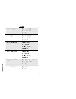
Страница 66: ...uantity 2 Rear turn indicator bulbs Type Spherical Colour Amber Power 12V 10W Quantity 2 Front turn indicator bulbs Type All glass Colour Amber Power 12V 5W Quantity 4 Tail light and stop light bulb Type Spherical double filament Power 12V 21 5W Quantity 1 License plate light bulb Type All glass Quantity 1 66 3 Maintenance ...

Страница 67: ...emblem off with a plain slot screwdriver 2 Remove the front shield connection unscrewing the two screws A 3 Remove the two screws B 4 Remove the screw C located in the expansion tank cover compartment 5 Remove the screw D located in the glove box compartment to the left of the shield back plate 6 Take the headlight assembly off its housing To reassemble repeat the operation in the reverse order 67...

Страница 68: ...03_29 03_30 68 3 Maintenance ...

Страница 69: ... that the edge of the beam projected on the screen is not more than 9 10 of the height of the centre of the headlight from the ground and not less than 7 10 3 Otherwise adjust the right headlight with the screw A that can be reached after removing the front shield union in the Front headlight assembly section N B THE ABOVE PROCEDURE COMPLIES WITH THE EUROPEAN STANDARDS RE GARDING MAXIMUM AND MINIM...

Страница 70: ...35 To replace the burnt out bulb remove the 3 screws shown in the figure and then take the rubber holder off its socket WARNING HIGH AND LOW BEAM BULBS ARE HALOGEN TYPE DO NOT TOUCH THEM WITH YOUR FINGERS TO AVOID DAMAGING THEIR FUNCTION 70 3 Maintenance ...

Страница 71: ...rate the screw indicated in the figure and remove glass C 03_37 Numberplatelight 03_37 Loosen the two screws D remove the plastic cover behind the mudguard Remove screw E from behind the mudguard Remove the bulb socket 71 3 Maintenance ...

Страница 72: ...ver F and replace the bulb 03_39 Brakelight 03_39 03_40 03_41 To remove the stop and tail light proceed as follows 1 Open the saddle and remove the rear cover unscrewing the two screws A 2 Remove the stop light glass cover unscrewing the four screws B 3 Turn and then remove the red bulb cover 72 3 Maintenance ...

Страница 73: ...03_43 To adjust mirrors loosen the lock nut A place the mirror stem adequately and tighten the lock nut The rear view mirror is assembled on a stem with a ball joint The mirror can be adjusted to the desired position manually 73 3 Maintenance ...

Страница 74: ...ing conditions the vehicle should be taken to a PIAGGIO GILERA Dealer or Authorised Service Centre CAUTION BRAKING SHOULD BEGIN AFTER ABOUT 1 3 OF THE BRAKE LEVER STROKE HAVE THE BRAKE PADS CHECKED BY THE DEALER ACCORDING TO THE CHECKS SPECIFIED IN THE TABLE OF SCHEDULED MAINTENANCE HOWEV ER IN THE EVENT OF NOISES COMING FROM THE FRONT AND OR REAR BRAKE SYSTEM DURING OPERATION IT IS ADVISABLE TO H...

Страница 75: ... event of a puncture contrary to the situation with a tyre with inner tube the tyre deflates more slowly resulting in a greater steering safety A flat tyre can be repaired with an emer gency inflate and repair spray In order to repair a tyre completely take your vehicle to a Piaggio Gilera Dealer or Authorised Service Centre The replacement of a type involves removing the wheel in question Take yo...

Страница 76: ...hly 1 second to turn the engine over slowly then insert the spark plug again 3 Ensure that the fuel tank is at least half full so that the fuel pump is fully covered spread antirust grease on the uncoated metal parts keep the wheels lifted above the ground by resting the chassis on two wooden wedges 4 As regards the battery follow the instructions in the Battery section Recommended products eni i ...

Страница 77: ... A HIGH PRESSURE WATER JET MACHINE ONLY USE THE FAN JET DO NOT PLACE THE WATER JET NOZZLE CLOSER THAN 60 CM NOT USE WATER AT A TEMPERATURE OF OVER 40ºC DO NOT USE THE JET AT HIGH PRESSURE DO NOT STEAM CLEAN DO NOT DIRECT THE JET AT WIRING AND SLOT DIFFUSER ON THE TRANS MISSION COVER CAUTION NEVER WASH THE SCOOTER IN DIRECT SUNLIGHT ESPECIALLY IN SUMMER WHEN THE BODYWORK IS STILL HOT AS THE SHAMPOO...

Страница 78: ...F Set the switch back to ON Side stand down Lift stand Fuse blown Replace the blown fuse and have the scooter checked by an Authorised Piaggio Gilera Service Centre STARTING DIFFICULTIES SEE SECTION DIFFICULT STARTING Lack of fuel in tank Refuelling Injection system fault Contact an Authorised Service Centre Fuel pump fault Contact an authorised Piaggio service centre Flat battery Recharge the bat...

Страница 79: ...NVERTER IGNITION PROBLEM Faulty spark plug Contact an Authorised Piaggio Gilera Service Centre Faulty ignition injection control unit Due to the presence of high voltage this element should only be checked by an expert Contact an Authorised Piaggio Gilera Service Centre LOW COMPRESSION Loose spark plug Screw in the spark plug tightly Cylinder head loose piston gas rings worn Contact an Authorised ...

Страница 80: ...uthorised Piaggio Gilera Service Centre Presence of air in the front and rear brake circuit Contact an Authorised Piaggio Gilera Service Centre INEFFICIENT SUSPENSIONS Shock absorber fault oil leak end buffer damaged shock absorber preloading incorrectly set Contact an Authorised Piaggio Gilera Service Centre AUTOMATIC TRANSMISSION IRREGULARITY Variators and or transmission belt damaged Contact an...

Страница 81: ...Nexus 250 i e Chap 04 Technicaldata 81 ...

Страница 82: ...04_01 82 4 Technicaldata ...

Страница 83: ...m Rear suspension Single arm with two double acting hydraulic shock absorbers and preloading adjustment in 4 positions Front brake Ø 260mm disc brake with hydraulic control activated by handlebar right side lever Rear brake Ø 240 mm disc brake with hydraulic control operated by the handlebar left side lever Front wheel alloy rim 14 x 3 50 Rear wheel alloy rim 14 x 3 50 Front tyres Tubeless 120 70 ...

Страница 84: ...0 l Air filter Sponge soaked in a mixture 50 SELENIA Air Filter Oil and 50 unleaded petrol ENGINE TECHNICAL DATA Version 250 cc i e Engine Single cylinder four stroke four valves Bore x stroke 72 x 60 mm Engine capacity 244 29 cm Compression ratio 10 5 11 5 1 Ignition advance before TDC variable integrated into the ignition system Engine idle speed 1700 100 rpm Spark plug CHAMPION RG 4 PHP 84 4 Te...

Страница 85: ...on system with variable timing and separate HV coil Lubrication With lobe pump inside the crankcase operated by a double filter chain mesh and paper filters Cooling Forced circulation coolant system Transmission Automatic expandable pulley speed variator V belt dry self ventilating automatic centrifugal clutch gear reduction unit and transmission casing with forced air circulation cooling Exhaust ...

Страница 86: ... A pair of pliers to extract fuses Wrench for adjusting shock absorbers The tools are stored in the helmet compartment 86 4 Technicaldata ...

Страница 87: ...Nexus 250 i e Chap 05 Sparepartsanda ccessories 87 ...

Страница 88: ...ALITY GUARANTEE AS THOSE INITIALLY FITTED ON THE SCOOTER THE USE OF NON ORIGINAL SPARE PARTS RENDERS THE WARRANTY VOID WARNING PIAGGIO MARKETS ITS OWN LINE OF ACCESSORIES THAT ARE RECOG NISED AND GUARANTEED FOR USE IT IS THEREFORE ESSENTIAL TO CON TACT AN AUTHORISED DEALER OR SERVICE CENTRE IN ORDER TO CHOOSE AND FIT ACCESSORIES CORRECTLY THE USE OF NON ORIGINAL ACCES SORIES MAY AFFECT THE STABILI...

Страница 89: ...RALLY GOOD CON DITION OR WHENEVER WEATHER CONDITIONS DEMAND IT SPEED SHOULD BE FURTHER REDUCED WARNING BE EXTREMELY CAREFUL WHEN INSTALLING AND REMOVING THE MECHAN ICAL ANTITHEFT DEVICE ON THE VEHICLE U SHAPED PADLOCK DISC BLOCK ETC MAINLY NEAR THE BRAKE PIPES TRANSMISSIONS AND OR ELECTRIC CA BLES AN INCORRECT INSTALLATION OR REMOVAL OF THE ANTITHEFT DEVICE AS WELL AS LEAVING IT ON BEFORE STARTING...

Страница 90: ...90 5 Sparepartsandaccessories ...

Страница 91: ...Nexus 250 i e Chap 06 Scheduledmaint enance 91 ...

Страница 92: ...serviced to the prescribed intervals of time even if you have not reached the predicted mileage Punctual vehicle servicing is necessary for the correct use of the guarantee For all further information regarding the Guarantee application modes and the execution of the Programmed Mainte nance refer to the Guarantee Booklet SCHEDULED MAINTENANCE TABLE km x 1 000 1 5 10 15 20 25 30 35 40 45 50 55 60 R...

Страница 93: ... AND CLEAN ADJUST LUBRICATE OR REPLACE IF NECESSARY C CLEAN R REPLACE A ADJUST L LUBRICATE Replace every 2 years RECOMMENDED PRODUCTS TABLE Product Description Specifications AGIP GEAR SAE 80W 90 Lubricant for gearboxes and transmissions API GL 4 eni i Ride PG 5W 40 Synthetic based lubricant for high performance four stroke engines JASO MA MA2 API SL ACEA A3 AGIP GP 330 Water repellent stringy cal...

Страница 94: ...e glycol based antifreeze fluid with organic inhibition additives Red ready to use ASTM D 3306 ASTM D 4656 ASTM D 4985 CUNA NC 956 16 AUTOSOL METAL POLISH Muffler cleaning paste special product for cleaning and polishing stainless steel muffler AGIP GREASE PV2 Ivory smooth textured slightly stringy anhydrous calcium base grease TL 9150 066 NATO G 460 symbol AGIP GREASE SM 2 Gray black smooth textu...

Страница 95: ...TABLE OF CONTENTS B Battery 59 C Checks 32 Clock 13 F Fuses 62 I Identification 27 K Keys 22 M Maintenance 45 P Puncture 75 R Refuelling 32 S Stand 40 41 T Toolkit 85 Tyres 51 V Vehicle 7 95 ...

Страница 96: ... changes to components parts or accessories which it considers necessary to improve the product or which are required for manufacturing or construction reasons Not all versions models shown in this publication are available in all countries The availability of each model should be checked at the official PIAGGIO sales network Copyright 2012 Piaggio C S p A All rights reserved Reproduction of this ...

Отзывы: