Gilera 633721 Скачать руководство пользователя страница 238

2

 - Prepare a graduated container with minimum

capacity of 100 cm3 and a resolution of 10-20 cm3

Connect the injector to the wire supplied with the

injection tester. The wire is provided with alligator

clips for direct connection to the battery.

Prepare an auxiliary battery.

Set the switch to "

ON

" with switch to "

RUN

" and

stand raised.

Select the "active diagnosis" function.

Start the pump diagnosis.

During the first 30 seconds of pump diagnosis,

power the injector by the wire and the auxiliary

battery for 15 seconds.

Collect the fuel delivered by the injector into the

graduated container.

Power supply pressure = 300 kPa (3 BAR)

Quantity delivered = approx. 40 cm3

YES go to 3 NO go to 4

3

 - Perform the injector sealing test.

Dry the injector outlet with a blast of compressed

air. Activate the fuel pump. Wait for one minute,

making sure there are no leaks coming from the

injector. Slight oozing is normal.

Value limit = 1 drop per minute

YES go to 5 NO go to 6

4

 - Higher quantities are not expected.

For lower quantities, replace the injector (THER-

MAL GROUP AND TIMING SYSTEM).

5

 - The injector is conforming.

6

 - Repeat the test. If the fault continues, replace

the injector (THERMAL GROUP AND TIMING

SYSTEM)

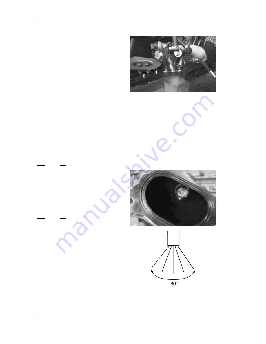
The injector atomisation cannot be checked by

simple methods. The injector is provided with 5

holes whose angulation forms a jet with a taper of

Injection

Nexus 500 euro 3

INJEC - 238

Содержание 633721

Страница 1: ...WORKSHOP MANUAL 633721 633728 Nexus 500 euro 3 ...

Страница 2: ...o components parts or accessories which it considers necessary to improve the product or which are required for manufacturing or construction reasons Not all versions shown in this publication are available in all countries The availability of single versions should be checked at the official Piaggio sales network Copyright 2005 PIAGGIO C S p A Pontedera All rights reserved Reproduction of this pu...

Страница 3: ...d the sections of this manual relating to special tools along with the special tool catalogue N B Provides key information to make the procedure easier to understand and carry out CAUTION Refers to specific procedures to carry out for preventing damages to the vehicle WARNING Refers to specific procedures to carry out to prevent injuries to the repairer Personal safety Failure to completely observ...

Страница 4: ......

Страница 5: ...STICS CHAR TOOLING TOOL MAINTENANCE MAIN ELECTRICAL SYSTEM ELE SYS ENGINE FROM VEHICLE ENG VE ENGINE ENG INJECTION INJEC SUSPENSIONS SUSP BRAKING SYSTEM BRAK SYS COOLING SYSTEM COOL SYS CHASSIS CHAS PRE DELIVERY PRE DE TIME TIME ...

Страница 6: ...INDEX OF TOPICS CHARACTERISTICS CHAR ...

Страница 7: ...he compressed air jet so as to not inhale the dust produced by the wear of the friction material Even though the latter contains no asbestos dust inhalation is harmful Maintenance rules Use original PIAGGIO spare parts and lubricants recommended by the Manufacturer Non original or non conforming spares may damage the vehicle Use only the special tools designed for this scooter Always use new gaske...

Страница 8: ...Engine prefix M351M Chassis prefix ZAPM35200 Dimensions and mass WEIGHT Specification Desc Quantity Dry weight 199 kg Width 765 mm Length 2090 mm Wheel base 1515 mm Saddle height 780 mm Height 1045 mm Characteristics Nexus 500 euro 3 CHAR 8 ...

Страница 9: ...stem with electric fuel pump Ø 38 mm throttle body and single injector Max power shaft 29 kW 39 CV at 7250 rpm Max torque shaft 40 N m 4 kgm at 5500 rpm Cooling system Fluid circulation through a motor driven pump 3 way thermo stat and electric fan Transmission TRANSMISSIONS Specification Desc Quantity Transmission With automatic expandable pulley variator with torque server V belt automatic clutc...

Страница 10: ...t brakes Twin discs of stainless steel dia 260 mm with floating calliper and twin 28 mm diameter plungers Brembo at front right and twin 26 mm diameter plungers Brembo at front left Rear brakes Disc of stainless steel dia 240 mm with fixed calliper and two opposed 34 mm diameter plungers Wheels and tyres WHEELS AND TYRES Specification Desc Quantity Rims in light alloy Front 3 50 x 15 Rims in light...

Страница 11: ... lower ring nut 10 13 Upper steering ring nut 36 39 Stem upper cap 35 55 Fixing screw handlebar to steering tube 45 50 Pumping element fixing screw 25 35 Safety screw on fork leg 6 7 Wheel fastening screws 33 37 tighten and loosen completely tighten and loosen by 90 REAR SUSPENSION Name Torque in Nm Engine chassis fixing pin 100 120 Central stand retainers 25 30 Muffler heat guard retainers 6 8 Si...

Страница 12: ...er 12 16 Engine oil drainage plug 24 30 Engine crankcase coupling screws 11 13 Oil pump screws 5 6 Gear mounting on crankshaft screws 10 12 Bulkhead screws for oil pump housing cover 8 10 FINAL REDUCTION Name Torque in Nm Rear hub cover screws 24 27 TRANSMISSION COVER Name Torque in Nm Driven pulley nut 92 100 Driving pulley nut 160 175 Anti vibration roller screw 16 7 19 6 M8 retainers for transm...

Страница 13: ...on Desc Quantity A 10 mm B 43 mm CATEGORIES OF COUPLING Name Initials Cylinder Piston Play on fitting Cylinder Piston A 91 990 91 997 91 954 91 961 0 029 0 043 Cylinder Piston B 91 997 92 004 91 961 91 968 0 029 0 043 Cylinder Piston C 92 004 92 011 91 968 91 975 0 029 0 043 Cylinder Piston D 92 011 92 018 91 975 91 982 0 029 0 043 N B THE PISTON MUST BE INSTALLED WITH THE ARROW FACING TOWARDS THE...

Страница 14: ...pes A and B to be matched A with A and B with B This selection is useful to keep the difference between the working distance of the gears and their distance without clearance at a given value in order to avoid abnormal noise TYPE A Specification Desc Quantity Centre to centre distance of the gears without clearance 76 937 76 867 Centre to centre distance on the crankcase 77 022 76 992 TYPE B Speci...

Страница 15: ...Quantity Cat 1 Standard diameter 40 010 40 016 Cat 2 Standard diameter 40 016 40 022 Crankshaft alignment Specific tooling 020335Y Magnetic support for dial gauge MAX ADMISSIBLE DISPLACEMENT Specification Desc Quantity A 0 15 mm B 0 010 mm C 0 010 mm D 0 10 mm Nexus 500 euro 3 Characteristics CHAR 15 ...

Страница 16: ...CE A IS A PROTRUSION OR RE CESS VALUE OF THE PISTON CROWN WITH RESPECT TO THE CYLINDER PLANE DISTANCE A HELPS DETERMINE THE THICKNESS OF GASKET B THAT HAS TO BE FITTED TO THE CYLINDER HEAD IN OR DER TO RESTORE COMPRESSION RATIO BASE GASKET B MUST BE THICKER THE MORE THE PLANE FORMED BY THE PISTON TOP PROTRUDES FROM THE PLANE FORMED BY THE CYLINDER HEAD ON THE OTHER HAND THE MORE THE PISTON TOP IS ...

Страница 17: ...Engine oil SAE 5W 40 API SL ACEA A3 JASO MA Synthetic oil AGIP BRAKE 4 Brake fluid FMVSS DOT 4 Synthetic fluid AGIP PERMANENT SPEZIAL coolant Monoethylene glycol based antifreeze fluid CUNA NC 956 16 AUTOSOL METAL POLISH Muffler cleaning paste special product for cleaning and polishing stainless steel muffler AGIP GP 330 Grease for brake levers throttle White calcium complex soap based spray greas...

Страница 18: ...INDEX OF TOPICS TOOLING TOOL ...

Страница 19: ...ing steering seats 001467Y002 Driver for OD 73 mm bearing 001467Y006 Pliers to extract 20 mm bearings 001467Y007 Driver for OD 54 mm bearings 001467Y008 Pliers to extract 17 mm ø bearings 001467Y014 Pliers to extract ø 15 mm bearings Nexus 500 euro 3 Tooling TOOL 19 ...

Страница 20: ... Pliers to extract ø 15 mm bearings 001467Y035 Belle for OD 47 mm bearings 002465Y Pliers for circlips 006029Y Punch for fitting fifth wheel seat on steer ing tube 020004Y Punch for removing fifth wheels from headstock Tooling Nexus 500 euro 3 TOOL 20 ...

Страница 21: ...steering tube ring nut 020150Y Air heater support 020151Y Air heater 020193Y Oil pressure gauge 020201Y Spacer bushing driving tube 020262Y Crankcase splitting strip 020306Y Punch for assembling valve seal rings Nexus 500 euro 3 Tooling TOOL 21 ...

Страница 22: ...escription 020329Y MityVac vacuum operated pump 020330Y Stroboscopic light to check timing 020331Y Digital multimeter 020333Y Single battery charger 020334Y Multiple battery charger Tooling Nexus 500 euro 3 TOOL 22 ...

Страница 23: ...c support for dial gauge 020357Y 32 x 35 mm adaptor 020358Y 37x40 mm adaptor 020359Y 42x47 mm adaptor 020360Y Adaptor 52 x 55 mm 020364Y 25 mm guide 020376Y Adaptor handle 020382Y012 bush valve removing tool Nexus 500 euro 3 Tooling TOOL 23 ...

Страница 24: ...code Description 020412Y 15 mm guide 020424Y Driven pulley roller casing fitting punch 020431Y Valve oil seal extractor 020434Y Oil pressure control fitting 020439Y 17 mm guide Tooling Nexus 500 euro 3 TOOL 24 ...

Страница 25: ...moving the driven pulley clutch 020456Y Ø 24 mm adaptor 020458Y Puller for lower bearing on steering tube 020459Y Punch for fitting bearing on steering tube 020460Y Scooter diagnosis and tester 020467Y Flywheel extractor Nexus 500 euro 3 Tooling TOOL 25 ...

Страница 26: ...on 020468Y Piston fitting band 020469Y Reprogramming kit for scooter diagnosis tester 020470Y Pin retainers installation tool 020471Y Pin for countershaft timing 020472Y Flywheel lock wrench Tooling Nexus 500 euro 3 TOOL 26 ...

Страница 27: ... Driving pulley lock wrench 020475Y Piston position checking tool 020476Y Stud bolt set 020478Y Punch for driven pulley roller casing 020479Y Countershaft lock wrench 020480Y Petrol pressure check set Nexus 500 euro 3 Tooling TOOL 27 ...

Страница 28: ...1Y Control unit interface wiring 020482Y Engine support 020483Y 30 mm guide 020512Y Piston fitting fork 020527Y Engine support base 020604Y011 Fitting adapter 020565Y Flywheel lock calliper spanner Tooling Nexus 500 euro 3 TOOL 28 ...

Страница 29: ...Stores code Description 020623Y Pre service gas extraction set 020625Y Kit for sampling gas from the exhaust manifold 020640y software euro3 Nexus 500 euro 3 Tooling TOOL 29 ...

Страница 30: ...INDEX OF TOPICS MAINTENANCE MAIN ...

Страница 31: ...eck AFTER 10 000 KM AFTER 30 000 KM AFTER 50 000 KM AND AFTER 70 000 KM Action Safety locks check Spark plug replacement Driving belt replacement Throttle lever adjustment Air filter check Air filter belt compartment check Engine oil change Valve clearance check Electrical system and battery check Coolant level check Brake fluid level check Engine oil replacement Brake pads check condition and wea...

Страница 32: ...Vehicle and brake test road test Hub oil check Stand control roller replace Crankcase breather empty Suspensions check Steering Check Injection system pipework visual check Fuel filter check Spark plug Check and replacement CAUTION THE SPARK PLUG MUST BE REMOVED WITH COLD EN GINE THE SPARK PLUG SHOULD BE CHECKED EVERY 6 000 KM AND REPLACED EVERY 12 000 KM THE USE OF NON CONFORMING IGNITION CONTROL...

Страница 33: ...h a recommended type Fit the spark plug with the correct inclination and manually screw it all the way down then use the special spanner to tighten it Locking torques N m Spark plug 12 14 Insert the cap onto the spark plug and proceed with the reassembly operations Hub oil Check Check the oil in the rear hub Characteristic Rear hub oil Capacity approximately 250 cc To check the rear hub oil level ...

Страница 34: ... dipstick again and make sure it is locked properly into place Replacement Prepare a suitable container Remove the oil filler plug shown in the figure Unscrew the oil drainage plug and drain out all the oil Tighten the drainage plug with its gasket and re fill Tighten the oil filler plug Characteristic Rear hub oil Capacity approximately 250 cc Recommended oil TUTELA ZC 90 Maintenance Nexus 500 eu...

Страница 35: ...ersing the removal procedure An inspection and possible cleaning with com pressed air of the air filter is scheduled every 6000 km in any case The air jet must be directed from the inside to the outside of the filter i e opposite the direction of the air flow during normal operation of the engine Any deposits of condensate out of the engine oil caused by blow by can be removed via the pipe shown i...

Страница 36: ...al especially if during the run in period Consumption levels in particular can be influenced by the conditions of use e g oil consumption increases when driving at full throttle Check This operation must be carried out with the engine cold and following the procedure below 1 Rest the vehicle on the central stand and on a flat ground 2 Unscrew the cap dipstick A dry it with a clean cloth and reinse...

Страница 37: ... a belt spanner for filters to remove cartridge filter C Make sure the pre filter and drain cap O rings are in good condition Lubricate them and refit the mesh filter and oil drain cap by tightening to the prescribed torque Refit a new cartridge filter making sure to lubri cate the O ring before fitting then screw until it comes into contact with the seal and further tighten to the prescribed torq...

Страница 38: ...s been star ted If the light comes on during braking at idling speed or while turning it is necessary to first switch off the engine and then to check the oil level and the lubrication system Checking the valve clearance To check the clearance in the valves collimate the references between the cam shaft control pul ley and head Use a feeler to make sure the clearance between the valve and register...

Страница 39: ... figure by loosening the 6 retaining screws Proceeding as described in chapter Engine partially drain the system and overhaul the pump Refill and drain the system again once after hav ing repaired the damaged and reinstalled all the components N B FOR CHANGING THE COOLANT AND BLEEDING THE SYSTEM SEE CHAPTER COOLING SYSTEM Characteristic Cooling system approx 1 8 litres Level check The coolant leve...

Страница 40: ...NT OF THE COOLANT AND THE FLUSHING OF THE SYSTEM SEE CHAPTER COOLING SYSTEM Braking system Level check Position the vehicle on a flat surface and on the centre stand Check the brake fluid level via the special indi cator located on the pump N B THE LEVEL TENDS TO DROP AS THE BRAKE PADS GET WORN A MINIMUM LEVEL SHOULD NOT BE REACHED IF THE LEVEL IS TOO LOW CHECK AND FIX THE SYSTEM SEALS IF RE QUIRE...

Страница 41: ...eristic Prescribed fluid TUTELA TOP 4 Under normal climatic conditions the fluid must be changed every 20 000 km or anyway every two years N B SEE THE BRAKING SYSTEM CHAPTER WITH REGARD TO THE CHANGING OF BRAKE FLUID AND THE BLEEDING OF AIR FROM THE CIRCUITS Headlight adjustment Place the scooter in use conditions with tyres inflated to the prescribed pressure on flat ground at 10 m from a white s...

Страница 42: ...unction of the injector and the spark plug Allow the engine to run using the starter and with the throttle body in fully open position as long as the gauge value is steady If the pressure is higher than specified remove the tool and reassemble the scooter If the pressure is less than indicated check the rpm at which the test is carried out if it is less than 450 rpm check the starter system If the...

Страница 43: ...INDEX OF TOPICS ELECTRICAL SYSTEM ELE SYS ...

Страница 44: ... 6 Stepping motor for idle nozzle 7 Electric fan 8 Engine temperature sensor 9 Remote control for electric fan 10 Overturn sensor 11 Injection load remote control 12 Key switch 13 Fuse box A 14 Main fuse 15 Fuse box B 16 Horn button 17 Horn 18 Engine stop remote control 19 Diode Electrical system Nexus 500 euro 3 ELE SYS 44 ...

Страница 45: ...urn indicator bulb 36 Twin filament bulb tail light stop light 37 Licence plate bulb 38 Right rear turn indicator bulb 39 Left front turn indicator bulb 40 Front right light assembly A Low beam light B Tail light 41 Front left light assembly B Tail light C High beam light 42 Right front turn indicator bulb 43 Headlight remote control 44 High beam passing mode switch 45 Light switch 46 Turn indicat...

Страница 46: ...ransmitter 57 Immobilizer decoder 58 Fuel injector 59 Spark plug 60 Tone wheel 61 HV coil 62 Lambda probe 63 Diagnostic socket 64 Fuel injection electronic control unit Ar Orange Az Sky Blue Bi White Bl Blue Gi Yellow Gr Grey Ma Brown Ne Black Ro Pink Rs Red Ve Green Vi Purple Components arrangement Diagnostic socket In order to access the diagnostic socket remove the supports of the passenger foo...

Страница 47: ... to access the high voltage coil remove the left hand side fairing Saddle opening ECU remote control Resetting of the remote control Electronic control unit ECU In order to access the immobilizer control unit re move the upper shield back plate Nexus 500 euro 3 Electrical system ELE SYS 47 ...

Страница 48: ...ABLE OR THE ELECTRONIC CONTROL UNIT RETIGHTEN THE SCREW AND THE GROUND CABLE Immobiliser decoder In order to access the immobilizer decoder re move the upper shield back plate Relays and diode group In order to access the relays and the diode group remove the upper shield back plate Voltage regulator In order to access the voltage regulator remove the lower cover Electrical system Nexus 500 euro 3...

Страница 49: ... on the exhaust manifold Conceptual diagrams Ignition KEY 3 Engine rpm sensor 11 Injection load remote control 12 Key switch 13 Fuse box A 14 Main fuse 15 Fuse box B 18 Engine stop remote control Nexus 500 euro 3 Electrical system ELE SYS 49 ...

Страница 50: ...mobilizer LED C Speedometer D Digital display E Engine Warning indicator light F Low fuel warning light G Oil warning light 55 Immobilizer aerial 57 Immobilizer decoder 59 Spark plug 61 HV coil 64 Fuel injection electronic control unit Battery recharge and starting KEY Electrical system Nexus 500 euro 3 ELE SYS 50 ...

Страница 51: ...ter motor 22 Start up remote control switch 23 Starter push button 24 Starter enable remote control 25 Engine stop switch 26 Centre stand switch 27 Rear brake stop button 28 Front brake stop button 36 Twin filament bulb position light stop light Level indicators and enable signals section KEY Nexus 500 euro 3 Electrical system ELE SYS 51 ...

Страница 52: ...se box B 18 Engine stop remote control 19 Diode 20 Battery 52 Oil pressure sensor 54 Instrument panel A Instrument panel light B Immobilizer LED C Speedometer D Digital display E Engine Warning indicator light F Low fuel warning light G Oil warning light 56 Fuel pump fuel level transmitter 58 Fuel injector 60 Tone wheel 62 Lambda probe 64 Fuel injection electronic control unit Electrical system Ne...

Страница 53: ...tric fan 12 Key switch 13 Fuse box A 14 Main fuse 15 Fuse box B 16 Horn button 17 Horn 18 Engine stop remote control 19 Diode 20 Battery 25 Engine stop switch 26 Centre stand switch 29 Saddle opener actuator 30 Saddle opener receiver 31 12V 180W socket Nexus 500 euro 3 Electrical system ELE SYS 53 ...

Страница 54: ...e 15 Scatola portafusibili B 20 Batteria 34 Predisposizione antifurto 35 Lampada indicatore di direzione posteriore Sx 36 Lampada doppio filamento Luce di posizione Luce stop 37 Lampada luce targa 38 Lampada indicatore di direzione posteriore Dx 39 Lampada indicatore di direzione anteriore Sx 40 Gruppo ottico anteriore Dx A Lampada anabbagliante B Luce di posizione Electrical system Nexus 500 euro...

Страница 55: ...Lampade illuminazione strumento B Led immobilizer C Tachimetro D Display digitale E Spia Warning motore F Spia Riservacarburante G Spia olio H Checks and inspections Immobiliser The electronic ignition system is controlled by the control unit with the integrated Immobilizer system The immobilizer is an anti theft system that allows the scooter to be operated only when it is started with coded keys...

Страница 56: ...terminals 17 23 and terminals 17 chassis ground continuous pow er supply In the event that there is no voltage check that fuse 1 has not blown and check the corresponding wiring With the key switch in position ON and the engine stop switch in RUN Battery voltage between terminals 26 23 and terminals 26 chassis ground continuous pow er supply In the event that there is no voltage check 1 The condit...

Страница 57: ...o ON for 2 seconds If you have copies of the key repeat the operation with each key Insert the MASTER key again and turn it to ON for 2 seconds The maximum time to change keys is 10 seconds A maximum of 7 service keys can be programmed at one time It is essential to adhere to the times and the pro cedure If you do not start again from the begin ning Once the system has been programmed master key t...

Страница 58: ...played after which the LED remains off permanently The keys can be stored to memory the vehicle can be started but with a limitation im posed on the number of revs 2 New decoder transponder missing or illegi ble The LED is permanently ON in this condition no operations are possible including starting of the vehicle 3 Decoder programmed service key inserted normal operating condition a single 0 7 s...

Страница 59: ...not present or is not detected Check the Immobilizer aerial wiring and change it if nec essary Diagnostic code 2 flashes A 2 flash code indicates a system where the de coder does not recognise the transponder signal This might depend on the inefficiency of the im mobiliser aerial or the transponder Turn the switch to ON using several keys if the code is repeated even with the Master key check the ...

Страница 60: ... the ground and the battery positive terminal passing through the 30A protective fuse This system therefore requires no connection to the key switch The three phase generator provides good recharge power and at low revs a good compromise is achieved between generated power and idle stability Stator check Stator winding check up WARNING THIS CHECK UP CAN BE MADE WITH THE STATOR PROPERLY INSTALLED 1...

Страница 61: ...EFORE CARRYING OUT THE CHECK MAKE SURE THAT THE BATTERY IS IN GOOD WORK ING ORDER 1 Place the vehicle on its centre stand 2 With the battery correctly connected to the circuit place the tester terminals between the battery terminals 3 Start the engine ensure that the lights are all out increase the engine speed and at the same time measure the voltage Electric characteristic Voltage ranging betwee...

Страница 62: ...igh beam low beam headlights 2 12V 55W halogen H7 2 Position light front headlight 2 12V 5W all glass 3 Turn indicator bulb 4 12V 10W spherical 4 Tail light bulb and light 1 12V 21 5W spherical twin filament 5 Licence plate bulb 1 12V 5W all glass 6 Helmet compartment bulb 1 12V 5W cylindrical Fuses The electrical system is equipped with 1 Six fuses A located on the shield back plate 2 Five fuses ...

Страница 63: ...rning light instrument panel permanent power supply light controller Designation Fuse 5 Threshold of operation 7 5 A Location Helmet compartment 6 Helmet compartment light socket 12V 180W anti theft device preparation Designation Fuse 6 Threshold of operation 15 A Location Helmet compartment FUSE HOLDER B Specification Desc Quantity 1 Immobilizer decoder power supply ignition ECU power supply Desi...

Страница 64: ... the front shield In order to access the remote control switches Remove the front shield Remove the front knee guard The following table shows the functions of each remote control switch Remote control switch Description A Immobiliser remote control switch B Electric fan remote control switch C Light remote control switch D Engine stop remote control switch E Electronic control unit remote control...

Страница 65: ...e kilometre reading for the symbol selected in SERVICE mode the date is also reset N B AT THE MOMENT THE DATE IS RESET THE SERVICE SYMBOL IS ACTIVATED AGAIN PERFORM THE RESET PROCEDURE ONLY AT THE MOMENT OF DELIVERY OF THE SCOOTER TO THE CUSTOMER IN ORDER THAT THIS SYMBOL SIGNALS THE NEED FOR THE FIRST SERVICE IN RELATION TO THE DISTANCE TRAVELLED AND THE TIME SINCE THE ACTIVATION The scooter has ...

Страница 66: ...metres Trip kilometres Clock N B IT IS POSSIBLE TO CHANGE THE DISPLAY TO KM OR MILES BY PRESSING THE BUTTONS MODE AND CLOCK SIMULTANEOUSLY FOR LONGER THAN 3 SECONDS AT THE MOMENT YOU TURN THE KEY TO POSITION ON THE WORD SET WILL BE DISPLAYED Pushing the MODE button for less than a second displays the following function sequence 1 Average speed The word MEAN appears together with km h or mph The va...

Страница 67: ... belt This lamp should come on and flash every 12000 km SERVICE Service coupon Indicates the need to carry out the scheduled maintenance operations The lamp should come on after reaching 1000 km or 1 year after initial activation then every 6000 km or 1 year after the last activation WARNING THE SCOOTER SHOULD BE SERVICED IN ANY CASE AT THE KILOMETRE INTERVALS INDI CATED IN THE OPERATING AND MAINT...

Страница 68: ...ed date Sealed battery Commissioning sealed batteries If the vehicle is provided with a sealed battery the only maintenance required is the check of its charge and recharging if necessary These operations should be carried out before delivering the vehicle and on a six month basis while the vehicle is stored in open circuit Besides upon pre delivery it is therefore necessary to check the battery c...

Страница 69: ...n the course of three months If it is necessary to refit the battery in the vehicle be careful not to reverse the connections remembering that the ground wire black marked must be connected to the negative clamp while the other two red wires marked must be con nected to the clamp marked with the positive sign Dry charge battery Remove the short closed tube and the caps then pour sulphuric acid int...

Страница 70: ...d it must therefore be recharged If the scooter is not used for a given time 1 month or more it will be necessary to periodically recharge the battery The battery runs down completely in the course of three months When refitting the battery onto the scooter pay attention not to invert the cables bearing in mind that the earth black wire marked with a must be connected to the negative terminal whil...

Страница 71: ...tone wheel connector on the system side Carry out the following measurements using the special tool Specific tooling 020331Y Digital multimeter Check the supply voltage Keeping the connector in the position shown in the photo check for battery voltage 12 V with the polarity shown If incorrect values are measured check the elec trical system and the digital instrument N B A DROP IN VOLTAGE OF 1 V I...

Страница 72: ... sensor 9 EMS diagnostic connector 10 EMS diagnostic connector 11 Throttle potentiometer signal 12 Engine rpm sensor 13 Injector control negative 14 Stepper motor Stepper motor 15 Injection telltale light 16 Decoder serial Overturn sensor 17 Battery powered 18 Air temperature sensor 19 Fuel pump 20 H V coil negative control 21 Stepper motor Stepper motor 22 Sensor power supply 23 Control unit nega...

Страница 73: ... 7 Ground lead 8 Not connected 9 Not connected 10 Selection input CH1 CH3 11 Positive output actuator 1 12 Data for alarm output Immobiliser decoder IMMOBILIZER DECODER Specification Desc Quantity 1 2 Immobilizer LED control negative 3 Base power supply positive 4 Negative 5 6 Electronic control unit EMS serial 7 8 Continuous power supply positive Immobilizer aerial Nexus 500 euro 3 Electrical sys...

Страница 74: ...t panel is provided with two connec tors A with 20 pins and B with 12 pins shown in the figure Connector A KEY 1 Wheel sensor 2 Wheel sensor signal 3 Wheel sensor 4 Lights 5 Engine rpm signal 6 Water temperature 7 Water temperature 8 Oil pressure 9 Right turn indicator Electrical system Nexus 500 euro 3 ELE SYS 74 ...

Страница 75: ...rning flashers Connector B KEY 1 Rpm indicator D 2 Rpm indicator B 3 4 5 ICP ID NEXUS 500 6 ICP ID NEXUS 250 7 Rpm indicator C 8 Rpm indicator A 9 10 11 12 ICP ID COMAND ID Analogue odometer ANALOGUE RPM INDICATOR Specification Desc Quantity 1 STEPPER MOTOR A 2 STEPPER MOTOR B 3 STEPPER MOTOR C 4 STEPPER MOTOR D Remote seat opening The vehicle is equipped with a remote control to open the saddle N...

Страница 76: ...e re mote control fails or if its range of operation is reduced To replace the batteries remove the three screws and uncouple the two half shells Electric characteristic Batteries used CR1616 Zeroing Remove the front shield to gain access to the re ceiver control unit seat opener controller Within the electrical wiring harness there are two cables one black ground and one black blue coming from pi...

Страница 77: ...the ON position all within four seconds 3 Wait 1 to 8 seconds 4 Repeat steps 2 and 3 for 4 times without removing the key The control unit confirms the programming has been successful by opening the saddle N B THE CONTROL UNIT CAN PROGRAMME UP TO 7 REMOTE CONTROLS Nexus 500 euro 3 Electrical system ELE SYS 77 ...

Страница 78: ...INDEX OF TOPICS ENGINE FROM VEHICLE ENG VE ...

Страница 79: ... at the cylinder head Remove the Lambda probe from its support and disconnect it Remove the screw indicated in the photograph Loosen the screw shown in the figure so as to loosen the muffler strap and remove the whole muffler Nexus 500 euro 3 Engine from vehicle ENG VE 79 ...

Страница 80: ... POSITIONING THE THROTTLE CONTROL TRANSMISSION PROPERLY Check that there is a small clearance when the valve is in abutment against the set screw Check the engine oil level and if necessary top it up with the recommended type Top up the cooling circuit Check the functioning of the accelerator and the electrical devices Removal of engine WARNING CARRY OUT THESE OPERATIONS WHEN THE ENGINE IS COLD Di...

Страница 81: ...return pipes from the carburettor and the cooling system piping outlet from the head and inlet to the thermostat Disconnect the HV cable from the spark plug Disconnect the alternator cable from the electrical system of the scooter WARNING BE VERY CAREFUL WHEN HANDLING FUEL CAUTION WHEN INSTALLING THE BATTERY ATTACH THE POSITIVE LEAD FIRST AND THEN THE NEG ATIVE LEAD Nexus 500 euro 3 Engine from ve...

Страница 82: ...INDEX OF TOPICS ENGINE ENG ...

Страница 83: ...f the cap Loosen the driven pulley shaft fastening nut using a misaligned wrench and prevent the pulley shaft rotation using a machine hexagon bush Remove the nut and the two washers N B DUE TO THE HIGH TIGHTENING TORQUE USING DIFFER ENT WRENCHES SUCH AS A CONVENTIONAL POLYG ONAL BUSH MAY DAMAGE THE HEXAGON OBTAINED ON THE SHAFT OR BREAK THE BUSH ITSELF Remove the six M6 screws Nexus 500 euro 3 En...

Страница 84: ...t the outside plastic transmission cover Air duct Remove the transmission cover Unscrew the two screws shown in the figure to remove the air conveyor Locking torques N m Air conveyor screws 11 12 Remove the external transmission cover Unscrew the 4 fastening screws shown in the fig ure to remove the external air conveyor Engine Nexus 500 euro 3 ENG 84 ...

Страница 85: ...ce and use the special tool so that it is adequately sup ported Pull out the bearing using the special tool N B BELL MUST BE PLACED INTO THE TRANSMISSION COV ER CLOSE TO THE BEARING SEAT AND THE WOODEN SURFACE SINCE WITHOUT BELL THE ENTIRE COVER STRUCTURE WOULD BEND NOT ONLY IN THE AREA OF MAXIMUM STURDINESS Specific tooling 001467Y002 Driver for OD 73 mm bearing 020376Y Adaptor handle 020375Y Ada...

Страница 86: ...cial tool N B PROPERLY SUPPORT THE OUTSIDE COVER TO PRE VENT DAMAGING THE PAINTED SURFACE Specific tooling 020376Y Adaptor handle 020358Y 37x40 mm adaptor 020439Y 17 mm guide Baffle roller Plastic roller Installation of belt anti vibration roller Install the anti flapping roller with the lip facing the engine crankcase Tighten the central screw to the prescribed tor que N B TURN THE DRIVEN AND OR ...

Страница 87: ...ROTATE FREELY REPLACE THE COMPLETE ROLLER Removing the driven pulley Remove the driven pulley assembly with the belt Inspecting the clutch drum Remove the clutch bell Check that the clutch bell is not worn or damaged Measure the clutch bell inside diameter N B CHECK THE ECCENTRICITY MEASURED 0 2 MM MAX Characteristic Max value 160 5 mm Standard value 160 2 mm Nexus 500 euro 3 Engine ENG 87 ...

Страница 88: ... figure CAUTION THE TOOL SHOULD BE FIRMLY SECURED IN A VICE USING THE SPECIAL TOOL DO NOT TIGHTEN THE REAR SCREW TOO MUCH AS THIS COULD CAUSE AN IRREVERSIBLE TOOL DEFORMATION USING THE SPECIAL 55 MM WRENCH REMOVE THE FASTENING RING NUT LOOSEN THE TOOL SCREW AND DISASSEMBLE THE DRIVEN PULLEY UNIT CLUTCH SPRING WITH SHEATH Specific tooling 020444Y Tool for fitting removing the driven pulley clutch P...

Страница 89: ...DING Specific tooling 020376Y Adaptor handle 020456Y Ø 24 mm adaptor 020363Y 20 mm guide N B IF YOU NEED TO OVERHAUL THE BEARINGS ON AN ASSEMBLED DRIVEN PULLEY UNIT IT IS NECESSARY TO SUPPORT THE UNIT BY THE BELL Specific tooling 001467Y002 Driver for OD 73 mm bearing Remove the roller bearing using the special tool supporting the fixed half pulley with the bell Specific tooling 020376Y Adaptor ha...

Страница 90: ...ide sealing rings and the 2 out side O rings Measure the movable half pulley bushing inside diameter Characteristic Maximum admissible diameter 50 05 mm Standard diameter 50 00 0 035 0 00 mm Refitting the driven half pulley bearing Install a new roller bearing using the special tool N B PLACE THE BEARING WITH THE WRITINGS AND THE EMBEDDED OIL GUARD FACING OUT WARDS Properly support the half pulley...

Страница 91: ...THE BASE OF THE HALF PULLEY Install the half pulley on the bushing being careful not to damage the top sealing ring during the in troduction Make sure the pins and collar are not worn re assemble the pins and collar Using a bent beak greaser lubricate the driven pulley unit with about 10 gr of grease this operation should be carried out through one of the two holes into the bushing to obtain the e...

Страница 92: ...ckness of the clutch mass friction material Characteristic Minimum thickness permitted 1 mm The masses must exhibit no traces of lubricants in that case check the driven pulley unit seals N B UPON RUNNING IN THE MASSES MUST EXHIBIT A CENTRAL CONTACT SURFACE AND MUST NOT BE DIFFERENT FROM ONE ANOTHER VARIOUS CONDITIONS CAN CAUSE THE CLUTCH TO TEAR Do not open the masses using tools to prevent a var...

Страница 93: ...e driven pulley clutch Compress the spring and insert the clutch on the driven pulley bushing N B BE CAREFUL NOT TO DAMAGE THE SHEATH OR THE BUSHING THREADED END Tighten the ring nut by hand and complete the tightening using the special wrench to the prescri bed torque Specific tooling 020444Y Tool for fitting removing the driven pulley clutch Locking torques N m Clutch ring nut 65 75 To facilitat...

Страница 94: ...ged Check the width of the belt Characteristic Minimum width 25 mm Standard width 26 2 mm Removing the driving pulley Using a 27 mm wrench turn the central pulley nut to horizontally align the central inside holes and install the special tool Specific tooling 020474Y Driving pulley lock wrench Engine Nexus 500 euro 3 ENG 94 ...

Страница 95: ...riving half pulley Remove the bushing connection washer Move the belt downwards Suitable support the roller contrast and extract the mobile driving half pulley with the relevant bushing and the rear washer being careful not to make the rollers come out Inspecting the rollers case Check that the inside bushings shown in the figure exhibit no signs of abnormal wear and measure the inside diameter CA...

Страница 96: ...d diameter Ø 29 959 mm Check that the rollers are not damaged or worn Characteristic Minimum admissible diameter Ø 24 5 mm Standard diameter Ø 24 9 mm Check the guide shoes for the variator back plate are not worn Check the wear of the roller housings and of the belt contact surfaces on both pulley halves Engine Nexus 500 euro 3 ENG 96 ...

Страница 97: ...riving half pulley and check that it is in contact with the spacer and with the guide bushing of the moving driving pulley Remove the flat washer and the spring washer as shown in the figure Insert the nut in the original position nut side in contact with the belleville washer Nexus 500 euro 3 Engine ENG 97 ...

Страница 98: ...ly engaged Finally install the tool by siding the nuts by hand and ensuring the tool is resting flatly Tighten the driving pulley fastening nut to the prescribed torque Remove the special tool Locking torques N m Driving pulley nut 160 175 Installing the roller container Install the spacer with the internal chamfer facing towards the inside Position the rollers on the half pulley as shown in the f...

Страница 99: ...driving pulley shaft cover positioning the tooth gap on the lower part with the reference mark on the transmission crankcase N B ENSURE THAT THE AIR INTAKE AND EXHAUST OPENINGS ARE COMPLETELY FREE Install the outside plastic transmission cover Tighten the 4 fastening screws to the prescribed torque Locking torques N m External transmission cover screws 7 9 Nexus 500 euro 3 Engine ENG 99 ...

Страница 100: ...ert the washers on the driven pulley shaft N B INSERT THE SMALLER WASHER FIRST THEN THE LARGER ONE Insert the flanged nut Prepare the torque wrench for LHS locking using a machine hexagon wrench Tighten the driven pulley shaft fastening nut using an offset wrench N B DUE TO THE HIGH TIGHTENING TORQUE USING DIFFER ENT WRENCHES SUCH AS A CONVENTIONAL POLYG ONAL BUSH MAY DAMAGE THE HEXAGON OBTAINED O...

Страница 101: ... screws Remove the hub cover and the relevant gasket Removing the wheel axle Remove the countershaft Remove the wheel axis complete with gear Removing the hub bearings Support the hub cover using the column kit Pull out the bearing using the special tool Specific tooling 020476Y Stud bolt set 001467Y006 Pliers to extract 20 mm bearings 001467Y007 Driver for OD 54 mm bearings Nexus 500 euro 3 Engin...

Страница 102: ...e special extractor to disassemble the bearing on the engine chassis of the countershaft Specific tooling 001467Y006 Pliers to extract 20 mm bearings 001467Y035 Belle for OD 47 mm bearings Removing the wheel axle bearings Take out the clip on the outside of the gearbox cover Support the hub cover using the column kit Pull out the bearing using the special tool Specific tooling 020476Y Stud bolt se...

Страница 103: ...ng Remove the oil guard using a screwdriver into the hub gear box Remove the Seeger ring shown in the figure Pull out the driven pulley shaft bearing from the engine crankcase using the special tool Specific tooling 020376Y Adaptor handle 020358Y 37x40 mm adaptor 020364Y 25 mm guide Inspecting the hub shaft Check that the 3 shafts exhibit no wear or defor mation on the grooved surfaces at the bear...

Страница 104: ...urface is not damaged or deformed Check the bearing bearings In case of faults replace the hub cover Refitting the driven pulley shaft bearing Heat the crankcase using the heat gun Specific tooling 020151Y Air heater Insert the driven pulley shaft bearing until it abuts against the bottom of the seat using the special tool N B PLACE IT WITH THE BALLS FACING THE HUB THIS AP PLIES TO BEARINGS WITH P...

Страница 105: ... bearing seat on the crank case Insert the gear shaft bearing in the upper crank case seat using the special tool N B PLACE IT WITH THE BALLS FACING THE HUB THIS AP PLIES TO BEARINGS WITH PLASTIC CAGE Specific tooling 020376Y Adaptor handle 020359Y 42x47 mm adaptor 020412Y 15 mm guide Place the safety lock Seeger ring of the driven pulley shaft bearing N B PLACE IT IN THE POSITION SHOWN IN THE FIG...

Страница 106: ... tool N B PLACE IT WITH THE BALLS FACING THE HUB THIS AP PLIES TO BEARINGS WITH PLASTIC CAGE Specific tooling 020376Y Adaptor handle 020360Y Adaptor 52 x 55 mm 020363Y 20 mm guide Heat the gear shaft bearing seat from the cover outside Insert the gear shaft bearing on the cover using the special punch until abutment Specific tooling 020376Y Adaptor handle 020360Y Adaptor 52 x 55 mm 020483Y 30 mm g...

Страница 107: ...r position of the centring dowels Install a new gasket Fit the gearbox cover making sure the breather pipe is in the correct position Position the 7 set screws tighten them to the prescribed torque being careful of the position of the bands holding the vent tube and the position of the 3 shortest screws as indicated in the figure Refill with the prescribed oil to the Max level Recommended products...

Страница 108: ...feed hoses and disconnect the return hose from the pump cover N B THE BANDS MUST BE REPLACED TO RE MOVE THEM OPEN WITH A SCREWDRIVER OR CUT THEM BE CAREFUL NOT TO DAMAGE THE PLASTIC UNIONS Removing the hub cover Drain the engine oil by removing the drainage cap Prepare a suitable container to collect the oil Remove the pre filter Engine Nexus 500 euro 3 ENG 108 ...

Страница 109: ...pport N B THE SCREWS ARE OF 4 DIFFERENT LENGTHS NOTE THE RELEVANT POSITIONS CAUTION REMOVE THE COVER AVOIDING ANY POSSIBLE INTERFERENCE BETWEEN STATOR AND ROTOR CAUTION BE CAREFUL TO PREVENT SLIPPAGE OF THE BY PASS VALVE AND OF THE RELEVANT SPRING Removing the flywheel cover components Loosen the six mounting screws and remove the water pump cover Nexus 500 euro 3 Engine ENG 109 ...

Страница 110: ...p seal Removing the stator Remove the two retaining screws and the cable guide bracket Unscrew the 3 fastening screws and remove sta tor and its wiring Loosen the two retaining screws and remove the reed valve support with bulkhead Engine Nexus 500 euro 3 ENG 110 ...

Страница 111: ...outlet union with the relevant O ring Remove the water pump impeller by unscrewing it from the relevant shaft N B THE THREADING IS CLOCKWISE IT IS ADVISABLE TO PREVENT THE SHAFT ROTATION BY INSERTING A 12 MM WRENCH INTO THE DRIVE Extract the shaft with the relevant abutment washer Nexus 500 euro 3 Engine ENG 111 ...

Страница 112: ...ant gas ket Remove the sealing ring for the pump shaft lu brication using a suitably shaped tool Remove the engine oil filling cap dipstick and the check hole cover for the distribution timing Remove the minimum oil pressure sensor Engine Nexus 500 euro 3 ENG 112 ...

Страница 113: ...RIATE PLIERS PAYING ATTENTION NOT TO CONSTRICT THE HOSES BUT ALSO TAKING CARE TO TIGHTEN THE CLAMPS SUF FICIENTLY Install the pre filter again and insert the engine oil drain plug tightening to the prescribed torque Refill the engine with the prescribed type of oil Recommended products AGIP CITY HI TEC 4T Engine oil SAE 5W 40 API SL ACEA A3 JASO MA Syn thetic oil Locking torques N m Engine oil dra...

Страница 114: ...ntains two types of cable Rigid cables close to the stator and flexible cables close to the connector Check that the winding is positioned so as not to interfere with the heads of the retaining screws Check that the mounting surface of the crankcase is not worn or deformed Check that the by pass valve seat the torque limiter and the water pump shaft are free from wear Characteristic By pass housin...

Страница 115: ...N THE CRANKCASE Locking torques N m Stator retainers 8 10 Install the wiring guide bracket tightening the 2 screws to the prescribed torque Locking torques N m Stator cable harness guide bracket screws 3 4 Temporarily install the distribution timing check hole cover and the engine oil filling cap bar Insert the blow by recovery duct using a new O ring Tighten the screws to the prescribed torque Lo...

Страница 116: ...fitting the flywheel cover components Before reassembling check that all components are perfectly clean For the cover carefully check all lubrication chan nels in particular The 3 by pass channels Oil feeding duct at the water pump shaft connec tion Pump drainage duct Engine Nexus 500 euro 3 ENG 116 ...

Страница 117: ...s to the prescribed torque Locking torques N m Supporting screws with bulkhead 0 3 0 4 Install a new sealing ring for the pump shaft using the special tool Install the oil minimum pressure sensor and tight en to the prescribed torque Specific tooling 020376Y Adaptor handle 020412Y 15 mm guide Locking torques N m Minimum oil pressure sensor 12 14 Nexus 500 euro 3 Engine ENG 117 ...

Страница 118: ...ng the flywheel cover seat Insert the mechanical seal on the shaft up to the impeller abutment surface N B THE FINAL INTRODUCTION DEPTH WILL BE DETER MINED BY THE IMPELLER Screw the impeller and tighten to the prescribed torque Locking torques N m Water pump impeller 4 5 Refitting the flywheel cover Lubricate the intermediate gear seat with torque limiter on the flywheel cover Align the water pump...

Страница 119: ...TION IS USEFUL PARTICULARLY IN THE EVENT OF REPAIRS WITH THE WATER PUMP COVER IN STALLED Install the flywheel cover on the engine paying attention to avoid interference between the stator and rotor WARNING FAILURE TO OBSERVE THIS INSTRUCTION MAY RESULT IN DESTRUCTION OF THE CERAMIC MAGNETS Tighten the 14 retaining bolts of the cover to the prescribed torque N B THE BOLTS HAVE FOUR LENGTHS THE 3 SH...

Страница 120: ...y connected to each other and to the frame YES go to 4 NO go to 5 3 Recharge and if necessary replace the battery 4 Connect the diagnostic tester see chapter Injection system Connect the induction clamp of an ammeter to the positive power supply cable of the starter motor Remove the 10A fuse no 12 see fuses chapter Switch in position ON with interrupt switch in position RUN and side stand raised S...

Страница 121: ... rotation example possible melting of the bushes and if no anomalies are found replace the starter motor 8 Low trailing speed Low electrical absorption Repeat the test bridging the power terminals of the starter remote control switch or even better replacing them Check the new values YES go to 12 NO go to 13 9 High trailing speed Low electrical absorption The engine turns too freely check the comp...

Страница 122: ...ne and the starter kinematic mechanism in the event of incorrect starting with consequent inverse rotations The freewheel is used for a sufficiently silent starting The starter control energised remote control is slaved to enabling signals by the side stand and the emergency OFF RUN switch which does not allow starting given dangerous conditions The starter control circuit is not controlled by the...

Страница 123: ... flywheel magneto N B IF YOU MUST REMOVE THE FLYWHEEL IT IS NECESSARY TO REMOVE THE CHAIN GUIDE SLIDING BLOCK RETAIN PLATE FIRST Unscrew the 3 fastening screws and remove the chain guide sliding block retain plate and the start up rim Align the holes obtained on the flywheel with the crankcase housing to allow the introduction of the special tool Nexus 500 euro 3 Engine ENG 123 ...

Страница 124: ...g sure that the pins are perfectly inserted in to the previously aligned holes and that it is per fectly abutted and almost flush with the flywheel Specific tooling 020472Y Flywheel lock wrench Loosen the magneto flywheel fastening nut Remove the special tool and the fastening nut Remove the washer Engine Nexus 500 euro 3 ENG 124 ...

Страница 125: ...SLIPPAGE WITH THE CONSEQUENT BREAKAGE OF THE MAGNETS Insert the special removing tool Using a 27 mm wrench and a 19 mm bushing release the flywheel Specific tooling 020467Y Flywheel extractor Remove the extractor Remove the nut and extract the flywheel with the start up rim Remove the crankshaft key To remove the start up rim from the freewheel it is necessary to turn it clockwise and pull it out ...

Страница 126: ...freewheel is coupled to the flywheel with high precision if removal is difficult use 2 screws as gripping points and as removing tools if required Extract the intermediate gear provided with tor que limiter Inspecting the flywheel components Check the integrity of the magnets Check that the magnet support cage is free from deformation or cracks Check that the flywheel splines exhibit no loos ening...

Страница 127: ...cteristic Inside diameter of the bushing Diameter 27 0 020 0 041 mm N B IF THE FAULTS DISCOVERED AFFECT THE HUB REPLACE THE STARTER RING GEAR AND FREEWHEEL IF ONLY THE BUSHING IS WORN IT IS POSSIBLE TO REPLACE ONLY THE COMPLETE START UP RIM IN THAT CASE CHECK ALSO THE DIAMETER AND THE SURFACE OF THE CONNEC TION ON THE CRANKSHAFT IN CASE OR IRREGULARITIES REPLACE THE CRANKSHAFT Intermediate gear Ch...

Страница 128: ...start up manoeuvres the lim iter prevents any kicks with consequent reversal of direction of the crankshaft which would impair the engine structure The limiter assembly cannot be overhauled In case of irregularities on the toothed discs replace the assembly Refitting the free wheel Make sure the freewheel faying surfaces are in good condition Thoroughly clean the free wheel to remove LOCTITE resid...

Страница 129: ...ng visible Lock the six clamping screws in criss cross fash ion to the prescribed torque Locking torques N m Screw fixing freewheel to flywheel 13 15 Oil the free wheel rollers Refitting the intermediate gear Lubricate the gear housing on the engine crank case Insert the intermediate gear with torque limiter Nexus 500 euro 3 Engine ENG 129 ...

Страница 130: ... turning it clockwise and inserting at the same time Refitting the flywheel magneto Insert the key on the crankshaft Install the flywheel checking the proper insertion of the key and engaging the torque limiter gear with the start up rim Insert washer and nut on the crankshaft Engine Nexus 500 euro 3 ENG 130 ...

Страница 131: ...72Y Flywheel lock wrench Align the 2 holes of the flywheel with the case housing to allow the introduction of the special tool Insert the special tool checking that the pins are perfectly introduced into the seat Specific tooling 020472Y Flywheel lock wrench Tighten the flywheel lock nut to the prescribed torque Locking torques N m Flywheel fixing nut 115 125 Nexus 500 euro 3 Engine ENG 131 ...

Страница 132: ...Chain guide sliding block retain plate fasten ing screws 3 4 Refitting the starter motor Check that the O ring is in good working order and lubricate it Insert the starter motor Tighten the 2 fastening screws to the prescribed torque Locking torques N m Starter motor screws 11 13 Cylinder assy and timing system Remove the external and internal transmission cover Remove the flywheel cover the flywh...

Страница 133: ... arms cover Loosen the 6 special screws with stop and the relevant rubber gaskets Remove the tappet cover with relevant gasket Removing the timing system drive Turn the engine to close the intake valves i e moving the reference on the tone wheel to the top as shown in the figure Nexus 500 euro 3 Engine ENG 133 ...

Страница 134: ...the valve lifting mass with relevant travel end washer N B BE CAREFUL NOT TO ALLOW THE WASHER AND SPRING TO FALL INTO THE ENGINE THROUGH THE CHAIN COM PARTMENT Align the references located on the tone wheel and on the head Loosen the central screw on the tensioner first Unscrew the 2 fastening screws and remove the tensioner with relevant gasket Engine Nexus 500 euro 3 ENG 134 ...

Страница 135: ...mshaft Remove the timing belt rim Remove the tone wheel Remove the engine revolution timing sensor and relevant O ring by loosening the fastening screw and removing the mounting band from the special hole obtained on the head gasket N B TO CHECK THIS COMPONENT SEE THE INJECTION CHAPTER Nexus 500 euro 3 Engine ENG 135 ...

Страница 136: ...MAY BE DIFFI CULT BE CAREFUL NOT TO DAMAGE THE INSIDE HEX AGON IF NECESSARY SEPARATE THE THREADS IN ADVANCE Remove the cam shaft Remove pins and rocking levers by the transmis sion side holes Removing the cylinder head Remove the spark plug Remove the cooling system outlet sleeve with thermostat Engine Nexus 500 euro 3 ENG 136 ...

Страница 137: ...the spark plug side with the thermostat support N B THE HEAD MAY BE REMOVED WITH THE CAMSHAFT ROCKING LEVER PINS AND FITTING BRACKET IF NECESSARY Loosen the 4 head cylinder fastening nuts in 2 or 3 times and in a crossed sequence Remove the head the 2 centring dowels the gasket and the lower chain guide sliding block N B DO NOT REMOVE THE DOWELS IF THEY ARE FORCED INTO THEIR SEAT CAUTION WHEN YOU ...

Страница 138: ... 020382Y012 bush valve removing tool CAUTION ARRANGE THE VALVES SO AS TO RECOGNISE THE ORIGINAL POSITION ON THE HEAD FLY WHEEL SIDE AND TRANSMISSION SIDE Remove the oil guards using the special tool Specific tooling 020431Y Valve oil seal extractor Remove the spring supports N B BLOW THE SEATS WITH COMPRESSED AIR TO FACILI TATE THE SPRING SUPPORT REMOVAL Engine Nexus 500 euro 3 ENG 138 ...

Страница 139: ...LINDER CAUTION TO PREVENT DAMAGES TO THE PISTON SUPPORT IT WHILE REMOVING THE CYLINDER Remove the 2 piston pin locking rings by the spe cific housings Extract the pin and remove the piston N B USE PAPER OR A CLOTH TO CLOSE THE CYLINDER HOUSING MOUTH ON THE CRANKCASE TO PREVENT SLIPPAGE OF ONE OF THE PIN LOCKING RINGS INTO THE CASE Remove the piston sealing rings and the oil scra per CAUTION NOTE T...

Страница 140: ...Check the pin outside diameter using a micrometer Characteristic Standard diameter 22 0 0 004 mm Calculate the coupling clearance between pin and connecting rod end Characteristic Standard clearance 0 015 0 029 mm Measure the diameter of the bearings on the piston Characteristic Standard diameter 22 0 006 0 001 mm Calculate the piston pin coupling clearance N B THE PIN HOUSINGS HAVE 2 LUBRICATION ...

Страница 141: ...lakes Check that the head matching surface exhibits no deformations or wear Characteristic Maximum allowable run out 0 05 mm Pistons and cylinders are classified into categories based on their diameter The coupling is carried out in pairs A A B B C C D D Carefully clean the seal housings Measure the coupling clearance between the seal rings and the grooves using suitable sensors as shown in the di...

Страница 142: ...he opening see figure of the sealing rings using a feeler gauge If higher values than those prescribed are meas ured replace the linings N B BEFORE REPLACING ONLY THE PISTON RINGS ENSURE THAT THE CLEARANCE BETWEEN THE PISTON RINGS AND THE PISTON RING GROOVES AND BETWEEN THE PISTON AND THE CYLINDER IS AS SPECIFIED IN ANY CASE NEW PISTON RINGS USED IN COMBINATION WITH A USED CYLINDER MAY HAVE DIFFER...

Страница 143: ...ific tooling 020470Y Pin retainers installation tool N B THE TOOL FOR INSTALLING THE STOP RINGS MUST BE USED MANUALLY CAUTION USING A HAMMER MIGHT DAMAGE THE STOPS HOUSING Choosing the gasket Provisionally fit the piston into the cylinder without any base gasket Install a comparator on the special tool using the short union as shown in the figure Specific tooling 020475Y Piston position checking t...

Страница 144: ...der base gasket to be used for reassembly by the table below Cor rectly identify the cylinder base gasket thickness to keep the correct compression ratio Remove the special tool and the cylinder N B IF DEVIATIONS OR RECESSES OR PROJECTIONS CLOSE TO THE CHANGE OF CATEGORY ARE MEASURED REPEAT THE MEASUREMENT AT THE OPPOSED SIDE TO DO SO REPEAT THE TOOL INSTALLATION BY INVERTING ITS POSITION Characte...

Страница 145: ...S ARE MADE WITH A TAPERED CYLINDRICAL CONTACT CROSS SECTION THIS IS TO ACHIEVE A BETTER BEDDING Misalign the lining openings at 120 as shown in the figure Lubricate the components with engine oil The engine uses the first compression lining with an L section Refitting the cylinder Insert the cylinder base gasket with the thickness determined above Using the fork and the ring clamp fit the cylinder...

Страница 146: ...ding component Inspecting the timing system components Check that the guide shoe and the tensioner shoe are not worn out Check that the crankshaft pinion and the cam shaft timing gear and crankshaft pinion exhibit no wear In case of wear of the sliding blocks replace them In case of wear of the chain or rim replace the en tire unit N B IF THE CHAIN HAS DAMAGED THE PINION REPLACE THE CRANKSHAFT AS ...

Страница 147: ... found to be interrupted at one or more points or is not flat re place the valve Inspecting the valve housings Clean the valve seats of any carbon residues Using the Prussian blue check the width of the impression on the valve seat V Measure the inside diameter of each valve guide Measure according to the rocking lever thrust di rection at three different heights Characteristic Standard value 1 1 ...

Страница 148: ...Outlet 4 945 mm Calculate the clearance between valve and valve guide Check the deviation of the valve stem by resting it on a V shaped abutment and measuring the extent of the deformation with a comparator Characteristic Limit values admitted 0 1 mm Check the concentricity of the valve head by ar ranging a comparator at right angle relative to the valve head and rotate it on a V shaped abutment C...

Страница 149: ...uantity Standard clearance 0 013 0 04 mm Admissible limit 0 08 mm OUTLET Specification Desc Quantity Standard clearance 0 025 0 052 mm Admissible limit 0 09 mm STANDARD VALVE LENGTH Specification Desc Quantity Inlet 95 0 0 3 mm Outlet 94 2 0 3 mm Check that there are no signs of wear on the surface of contact with the articulated register terminal Nexus 500 euro 3 Engine ENG 149 ...

Страница 150: ...guide see figure CAUTION TO AVOID SCORING THE FAYING SURFACE DO NOT KEEP ROTATING THE VALVE WHEN NO LAPPING COMPOUND IS LEFT CAREFULLY WASH THE CYLINDER HEAD AND THE VALVES WITH A SUITABLE PRODUCT FOR THE TYPE OF LAPPING COMPOUND BEING USED CAUTION DO NOT REVERSE THE FITTING POSITIONS OF THE VALVES RIGHT LEFT Inspecting the springs and half cones Check that the upper spring caps and the cotter hal...

Страница 151: ...ve cotters equipped with part 012 removal tool 020382Y012 bush valve removing tool N B DO NOT CHANGE THE VALVE FITTING POSITION FIT THE VALVE SPRINGS WITH THE REF ERENCE COLOUR ON COTTER SIDE TURNS WITH GREATER PITCH Inspecting the cam shaft Check that the camshaft bearings exhibit no scores or abnormal wear Using a micrometer measure the camshaft bearings STANDARD DIAMETER Specification Desc Quan...

Страница 152: ...he defective components with new ones Check that the retaining plate seat shown in the figure exhibits no wear Check that the automatic valve lifting device cam the travel end roller and the rubber abutment on the containment bell are free from wear Check that the valve lifting spring has not yielded Replace any defective or worn components Check that the rocking lever pins exhibit no scores or we...

Страница 153: ...d cylinder Install the head gasket N B THE FIGURE SHOWS THE INSERTION POSITION OF THE TWO CENTRING DOWELS BETWEEN HEAD AND CYLINDER THE DIRECTION OF INSTALLATION FOR THE GASKET IS FORCED BY THE DOWELS The head gasket is made of steel and has a standard thickness Check that the head lubrication channel is per fectly clean Clean with compressed air jets if required Insert the head Lubricate the stud...

Страница 154: ...o the prescribed torque Locking torques N m Exhaust intake head fixing nuts 10 12 Tighten the 3 side screws to the prescribed tor que Locking torques N m Head fixing screws 10 12 Install the coolant temperature sensor with the washer and tighten to the prescribed torque CAUTION FAILURE TO OBSERVE THE TIGHTENING TORQUE CAN DAMAGE THE SENSOR Locking torques N m coolant temperature sensor 10 12 Insta...

Страница 155: ...flywheel side Lubricate the two rocking levers through the holes at the top Clean the camshaft by blowing with little com pressed air jets especially the retaining plate housing Lubricate the 2 shafts Insert the camshaft into the head with the cams opposite the rocking levers Remove any LOCTITE residues from the screws fixing the camshaft retaining bracket using a brush Apply the recommended produ...

Страница 156: ... the housing of the tone wheel timing peg are free from deformations or dents Insert the wheel speed sensor on the camshaft keeping the stroke reference visible Install the engine revolution timing sensor using a new O Ring orientating it as shown in the figure Tighten the 2 fastening screws to the prescribed torque N B TO CHECK THIS COMPONENT SEE CHAPTER INJEC TION Locking torques N m Rpm timing ...

Страница 157: ... INSTALL THE FLYWHEEL COVER WITHOUT THE COOLING SYSTEM SLEEVES Using the TORX wrench remove the timing check cap Align the wheel speed sensor references with the head as shown in the figure Keeping the belt slightly pulled turn the crank shaft using the driving pulley to make the reference on the magnet support collimate with that on the flywheel cover Nexus 500 euro 3 Engine ENG 157 ...

Страница 158: ...ng screw Lock the mass fixing screws to the prescribed torque using the recommended product Recommended products Loctite 243 Medium strength threadlock Loctite 243 medium strength threadlock Locking torques N m Counterweight screw 7 8 5 Remove the central screw Install the valve lifting mass being careful to the proper positioning of the travel end ring Lubricate the mass and de compressor control...

Страница 159: ...dlock Check that the decompression mass is free and that it is pulled by the spring Locking torques N m Valve lifter mass stop bell fixing screws 30 35 Place the engine with the valve clearance adjustment timing references aligned with the head Check the clearance between valve and rocking lever using a thickness gauge PRESCRIBED CLEARANCE Specification Desc Quantity Inlet 0 15 mm engine cold drai...

Страница 160: ... check whether the ignition advance determined by the injection system matches the value actually activated on the engine by means of the stroboscopic light Specific tooling 020460Y Scooter diagnosis and tester 020330Y Stroboscopic light to check timing Proceed as follows Remove the outside transmission cover as de scribed in the automatic transmission chapter Remove the TDC reference inspection c...

Страница 161: ... position 1 spark 2 revs Check that the real values of rpm and ignition advance match those measured using the diag nostic tester Specific tooling 020460Y Scooter diagnosis and tester If the values do not match check distribution timing rpm timing sensor injection control unit Inspecting the radial air gap Align a tooth of the tone wheel with the revolution timing sensor Check the air gap using a ...

Страница 162: ...ener on the cylinder using a new gasket Tighten the two fastening screws to the prescri bed torque Locking torques N m Tightener fastening screws 11 13 Insert the spring with the central screw and the washer Tighten the central screw to the prescribed tor que Locking torques N m Tightener screw 5 6 Engine Nexus 500 euro 3 ENG 162 ...

Страница 163: ... the remaining 4 screws in a crossed se quence 3 4 5 6 N B CHECK THE PROPER POSITION OF THE GASKET Locking torques N m Tappet cover fixing screws 7 9 Install the transmission cover and the relevant net filter and the outside transmission cover as descri bed in the Automatic transmission chapter Install the cooling system sleeves using new bands as described in the Flywheel cover chap ter Nexus 500...

Страница 164: ... N m Inlet manifold screws 11 13 Crankcase crankshaft Remove the outside and inside transmission cov er and the complete driving pulley as described in Automatic transmission Remove the flywheel cover with the cooling sys tem sleeves as described in the Flywheel cover chapter Remove the flywheel with the starting system fol lowing the instruction given in Flywheel and Start ing system Engine Nexus...

Страница 165: ...th special tool comparator Specific tooling 020262Y Crankcase splitting strip 020335Y Magnetic support for dial gauge Characteristic Standard clearance 0 10 0 50 mm Admissible increase limit after use 0 60 mm Upper clearances are an indication of wear on the surfaces of the crankshaft casing support To carry out an accurate measurement measure the clearance in both directions between crankcase and...

Страница 166: ...aft inserted on the flywheel side half crankcase Remove the coupling gasket N B THE BUSHING SUPPORT CAN BE LEFT IN THE FLY WHEEL SIDE HALF CRANKCASE Removing the crankshaft Before removing the crankshaft check the timing with the countershaft To carry out this check turn the crankshaft to align the two holes obtained on the crankshaft with the hole on the countershaft control gear This is an optim...

Страница 167: ... trol gear To remove the control gear loosen the 4 fasten ing screws Remove the gear only if actually required CAUTION THE SCREWS HAVE A COUNTERSUNK HEAD AND THEIR THREADING IS LOCKED BY LOCTITE BE CAREFUL NOT TO DAMAGE THE CONTROL HEXAGON TO OBTAIN BET TER RESULTS IT IS PREFERABLE TO USE AN INSIDE HEXAGON SOCKET WRENCH Removing the countershaft Place the special tool as shown in the figure Specif...

Страница 168: ... inside Seeger ring Upturn the half crankcase Remove the bearing from the flywheel side half crankcase using the special tool and a mallet Specific tooling 020376Y Adaptor handle 020358Y 37x40 mm adaptor 020439Y 17 mm guide Remove the bearing from the transmission side half crankcase using the special tool Specific tooling 001467Y008 Pliers to extract 17 mm ø bearings 001467Y007 Driver for OD 54 m...

Страница 169: ...stall the new bearing on the half crankcase us ing the special tool N B IF A BEARING WITH PLASTIC CAGE IS USED KEEP THE BALLS VISIBLE FROM THE CRANKCASE INTERNAL SIDE Specific tooling 020376Y Adaptor handle 020359Y 42x47 mm adaptor 020439Y 17 mm guide Fit the Seeger ring Before installing the new bearing on the trans mission side crankcase heat the seat using the special tool Specific tooling 0201...

Страница 170: ...e crankshaft components Check the axial clearance on the connecting rod Characteristic Standard clearance 0 20 0 40 mm Check the connecting rod diametrical clearance Characteristic Standard clearance 0 046 0 076 mm Check the surfaces that limit the axial free play are not scored and measure the width of the crank shaft between these surfaces as shown in the diagram N B BE CAREFUL NOT TO LET THE ME...

Страница 171: ...clearance is higher than the standard value and the crankshaft exhibits no irregularity the problem is caused by wear or by a wrong machining on the engine crankcase Check the diameters of both the bearings of the crankshaft in accordance with the axes and surfa ces shown in the figure Half shafts are classified into two categories Cat 1 and Cat 2 STANDARD DIAMETER Specification Desc Quantity Cat ...

Страница 172: ...k the connecting rod small end diameter see chapter Thermal group and timing system When cleaning the crankshaft be careful to prevent any impurity from entering into the shaft lubrication hole N B IN CASE OF REPLACEMENT OF A CRANKSHAFT CONSISTING OF TWO HALF SHAFTS OF DIF FERENT CATEGORY REPLACE THE TWO HALF CRANKCASES AS WELL COUPLING THE TWO COMPONENTS SHAFT AND CRANKCASE WITH THE SAME CATEGORY...

Страница 173: ...R IT IS ESPECIALLY IMPORTANT THAT THE BY PASS HOUSING ON THE FLYWHEEL COVER IS FREE FROM WEAR THAT MAY IMPAIR THE PROPER SEALING OF THE LUBRICATION PRESSURE ADJUSTMENT PISTON THE HEAD LUBRICATION CHANNEL IS EQUIPPED WITH A SHUTTER JET THIS GIVES A LOW PRESSURE HEAD LUBRICATION THIS CHOICE WAS MADE TO REDUCE THE OIL TEMPERATURE IN THE SUMP The jet clogging impairs the head lubrication and the timin...

Страница 174: ...ared with the crankshaft axial clearance of the limiting surface N B TO KEEP THE BUSHINGS ON THE CRANKCASE IN SUCH POSITION DRIVING IS FORCED ON CAST IRON RINGS INSERTED IN THE CASTING OF BOTH CRANKCASE HALVES Check the inside diameter of the main bushings in the three directions indicated in the diagram Repeat the measurements for the other bushing half see diagram N B DO NOT TAKE THE MEASUREMENT...

Страница 175: ...ies Spare shafts have half shafts of the same category N B TO REPLACE THE HALF SHAFTS REMOVE THE COUNTERSHAFT BEARINGS AS DESCRIBED ABOVE REMOVE THE COMPLETE DRIVEN PULLEY AND THE ANTI FLAPPING ROLLER FROM THE TRANSMISSION SIDE HALF CRANKCASE AS DESCRIBED IN CHAPTER AUTOMATIC TRANSMISSION AND THE HUB COVER WITH THE RELEVANT GEARS AND BEARINGS AS DESCRIBED IN CHAPTER FINAL REDUCTION Countershaft Us...

Страница 176: ...fastening screws Insert the control gear on the crankshaft with the hole countersink visible Tighten the 4 fastening screws to the prescribed torque N B TO AVOID DAMAGING THE SCREW CONTROL HEXAGON IT IS PREFERABLE TO USE AN IN SIDE HEXAGON SOCKET WRENCH Locking torques N m Gear mounting on crankshaft screws 10 12 Lubricate the main bearing on the flywheel side half crankcase Lubricate the shim adj...

Страница 177: ...l pump closing plate Tighten the 2 flanged fastening screws to the prescribed torque Locking torques N m Bulkhead screws for oil pump housing cover 8 10 Refitting the crankcase halves Remove the oil guard from the transmission side half crankcase using a screwdriver Install a new oil guard after lubricating it using the special tool arranging it at a 0 5 mm recess from the crankcase plane CAUTION ...

Страница 178: ...out tightening Insert the 14 fastening screws by arranging the single shorter screw A and the single longer screw B as shown in the figure Tighten the screws thoroughly and tighten to the prescribed torque Check that the crankshaft rotates freely N B REMOVE ANY EXCESS FROM THE CRANKCASE COUPLING GASKET ON THE CYLINDER PLANE TO ENSURE BETTER SEALING PERFORMANCE Locking torques N m Engine crankcase ...

Страница 179: ... the relevant mesh filter and the outside transmission cover as described in the section Automatic transmission See also Cylinder assy and timing system Flywheel cover Lubrication TECHNICAL SPECIFICATIONS SUMP CAPACITY Specification Desc Quantity Overhaul 1 7 l Oil and filter replacement 1 5 l RECOMMENDED ENGINE OIL Product Description Specifications AGIP CITY HI TEC 4T Engine oil SAE 5W 40 API SL...

Страница 180: ...pecification Desc Quantity Type mesh plastic OIL FILTER Specification Desc Quantity Type Paper with pressure relief and anti drain back by pass valves OIL MINIMUM PRESSURE INDICATOR LIGHT SWITCH Specification Desc Quantity Calibration 0 3 0 6 bar HEAD LUBRICATION CONTROL JET Specification Desc Quantity Diameter 1 0 05 mm Tightening torque 5 7 N m PISTON COOLING NOZZLE Specification Desc Quantity D...

Страница 181: ...ics The lubrication system is divided into two sections High pressure Low pressure The high pressure section includes all components located on the engine crankcase whereas the low pressure section only refers to the thermal group The trochoidal pump is installed in the sump and is controlled by a pair of gears To guarantee the integrity of the pump a pre filter is fitted This is a screw in type p...

Страница 182: ... compensated by the oil supplied to the smaller diameter bearing The camshaft supplies the lubricant to the rocking levers via the holes provided these are installed in a position to ensure that the lubrication is maintained even after the scooter has stopped This is ach ieved when the camshaft reaches its most usual and likely position when the engine is shut off The oil used to lubricate the hea...

Страница 183: ...limetres Specific tooling 020331Y Digital multimeter AHEAD go to 5 5 Measure the pressure with cold and idling engine STANDARD VALUES Specification Desc Quantity 20 C Temperature 1400 rpm approx 4 5 bar N B RPM CAN BE MEASURED BOTH BY THE EXHAUST GAS ANALYSER AND BY THE DIAGNOSTIC TESTER Specific tooling 020460Y Scooter diagnosis and tester YES go to 6 NO go to 12 6 Let the engine warm up and repe...

Страница 184: ...place the faulty components Flywheel cover chapter 16 Overhaul the engine Crankcase and crankshaft chapter 17 Open the engine crankcase and remove the oil pump as described in the Crankcase and crank shaft chapter Check the oil pump as described in the following pages Check that the cooling nozzle and the timing system feeding jet are properly installed Visually inspect the crankshaft couplings an...

Страница 185: ...THE SYSTEM PRESSURE 1 If oil consumption is above 250 g 1000 km on a run in engine proceed as follows AHEAD go to 2 2 Check the presence of oil at the scavenge duct on the filter box YES go to 3 NO go to 4 3 Check the one way reed valve and the decantation chamber drainage hole YES go to 5 NO go to 4 4 Check the thermal group seals piston rings valve guides and oil guards see Thermal group and Tim...

Страница 186: ... the 2 retaining screws through the eyes machined in the gearing proper Remove the gasket Remove the two screws and the oil pump cover Remove the inside rotor retaining snap ring turn ing it to move the opening at the shaft face Engine Nexus 500 euro 3 ENG 186 ...

Страница 187: ...shaft with the gear and install the lock ring then turn it with the opening opposed to the shaft face Check any irregular clearance between shaft and pump body Using a thickness gauge check the distance be tween the rotors in the position shown in the figure Characteristic Admissible limit clearance 0 012 mm Check the distance between external rotor and pump body see figure Characteristic Admissib...

Страница 188: ...pump see the Lubrication chapter Refitting Make sure the gasket is in the correct position N B THE TOOTH OF THE GASKET MUST BE IN ITS SEAT Insert the oil pump with gear Insert the 2 retaining screws through the slots on the gear and tighten to the prescribed torque N B THE ASSEMBLY POSITION OF THE PUMP IS FIXED BY INSTALLATION OF THE SCREWS Engine Nexus 500 euro 3 ENG 188 ...

Страница 189: ...the nut Tighten the nut to the prescribed torque using the recommended product Remove the special tool Recommended products Loctite 243 Medium strength threadlock Loctite 243 medium strength threadlock Locking torques N m Countershaft fixing nut 25 29 Lubricate the internal rotors Check there are no signs of scoring or wear on the oil pump cover If non conforming values or signs of wear are found ...

Страница 190: ...Oil pump cover screws 0 7 0 9 Engine Nexus 500 euro 3 ENG 190 ...

Страница 191: ...INDEX OF TOPICS INJECTION INJEC ...

Страница 192: ...nstant based on the ambient pressure The fuel supply circuit consists of Fuel pump Fuel filter Injector Pressure regulator The pump the filter and the regulator are placed inside the fuel tank on a single support The injector is connected by two pipes provided with quick couplings This allows obtaining a continuous circulation thereby avoiding the risk of fuel boiling The pressure regulator is sit...

Страница 193: ...stic tester is also required to adjust the idle mixture Specific tooling 020460Y Scooter diagnosis and tester The EMS injection ignition system has a control function over the rpm indicator and the radiator cooling electric fan The EMS is connected to the anti theft immobilizer system decoder In turn the decoder is connected to a flashing di agnostic LED that also serves as deterrent The EMS contr...

Страница 194: ...ectric components and wiring 8 When an ignition fault is detected start the checks from the battery and the injection system con nections 9 Before disconnecting the EMS control unit connector perform the following operations in the following order Set the switch to OFF Disconnect the battery Failure to respect this norm may damage the control unit 10 Do not invert the polarity when fitting the bat...

Страница 195: ...nnector 10 EMS diagnostic connector 11 Throttle potentiometer signal 12 Engine rpm sensor 13 Injector control negative 14 Stepper motor Stepper motor 15 Injection telltale light 16 Decoder serial Overturn sensor 17 Battery powered 18 Air temperature sensor 19 Fuel pump 20 H V coil negative control 21 Stepper motor Stepper motor 22 Sensor power supply 23 Control unit negative 24 Stepper motor Stepp...

Страница 196: ...D control negative 3 Base power supply positive 4 Negative 5 6 Electronic control unit EMS serial 7 8 Continuous power supply positive Immobilizer aerial EMS circuit diagram KEY 3 Engine rev sensor 4 Throttle valve position sensor Injection Nexus 500 euro 3 INJEC 196 ...

Страница 197: ...D C Speedometer D Digital display E Engine Warning indicator light F Low fuel warning light G Oil warning light 55 Immobilizer aerial 56 Fuel pump fuel level transmitter 58 Fuel injector 60 Tone wheel 62 Lambda probe 63 Diagnostic socket 64 Fuel injection electronic control unit Troubleshooting procedure This section makes it possible to find what solutions to apply when troubleshooting Engine doe...

Страница 198: ... relay H V coil Injector revolution timing sensor Air temperature Coolant temperature Atmospheric pressure Start up engine speed Starter motor and remote control Battery Ground connections End of compression pressure End of compression pressure Power to the spark plug Spark plug Shielded cap HV coil Rpm timing sensor Ignition advance Fuel supply Fuel pressure low Injector capacity low Injector sea...

Страница 199: ... RETURN TO THE IDLING SPEED IDLING SPEED TOO HIGH Possible Cause Operation Presence of faults detected by the self diagnosis Pump relay H V coil Injector revolution timing sensor Air temperature Coolant temperature Atmospheric pressure Ignition efficiency Ignition timing Correctness of the parameters Throttle valve position sensor Stepper Coolant temperature sensor Intake air temperature sensor In...

Страница 200: ...er Trimmer value adjustment CO adjustment Engine revs irregularly IRREGULAR PROGRESS OF THE ENGINE WITH VALVE SLIGHTLY OPEN Possible Cause Operation Presence of faults detected by the self diagnosis Pump relay H V coil Injector revolution timing sensor Air temperature Coolant temperature Atmospheric pressure Intake system cleaning Air filter Diffuser and throttle valve Additional air pipe and Step...

Страница 201: ...upply Fuel level in the tank Fuel pressure Fuel filter Injector capacity Engine knocking PRESENCE OF KNOCKING OVERHEAD KNOCKING Possible Cause Operation Presence of faults detected by the self diagnosis Pump relay H V coil Injector revolution timing sensor Air temperature Coolant temperature Atmospheric pressure Ignition efficiency Spark plug Parameter reliability Throttle valve position signal Co...

Страница 202: ...tooling 020460Y Scooter diagnosis and tester 1 Check whether the immobiliser system LED in dicates that the switch is in position ON and that the deterrent flashing is on YES go to 2 NO go to 7 2 The decoder is properly programmed YES go to 3 3 Switch set to ON with side stand raised and emergency switch set to OFF The injection tell tale light turns on for about 3 seconds YES go to 5 NO go to 4 4...

Страница 203: ...l tool to check the control unit power supply Pin 17 battery positive Pin 23 battery negative YES go to 12 NO go to 13 12 Control unit with proper base power supply 13 If the battery negative is not present check continuity between Pin 23 of the special tool and earth Detect the presence of the battery positive on Pin 17 of the special tool and on pin 3 of the decoder connector YES go to 12 NO go ...

Страница 204: ...nit and injection system YES go to 7 Specific tooling 020481Y Control unit interface wiring 6 Fix any short circuits and replace the fuse Check decoder and control unit if necessary YES go to 1 7 Disconnect the main decoder connector and check the following conditions switch set to ON switch to RUN and side stand raised Terminal no 8 battery positive Terminal no 4 battery negative YES go to 8 NO g...

Страница 205: ...ON Pin B F Continuity YES go to 14 14 Check the engine stop remote control switch connector and the switch efficiency The connector can be recognised by its larger section white lead 85 86 approx 70W YES go to 15 N B CHECK THE COIL RESISTANCE 15 Check the signal circuit emergency switch and connector side stand switch and connector YES go to 16 16 Check the cable harness continuity Check the utili...

Страница 206: ...us power supply for 10 seconds and switch to ON again if the message is still displayed proceed as fol lows 1 Check the diagnostic tester connections YES go to 2 NO go to 3 2 Check the control unit base and continuous power supplies YES go to 4 3 Restore 4 Place the special tool between control unit and system Keep the control unit disconnected YES go to 5 Specific tooling 020481Y Control unit int...

Страница 207: ...stic socket PIN 9 control unit con tinuity 10 23 insulation 1 MΩ 9 23 insulation 1 MΩ YES go to 6 NO go to 7 6 The circuit is in good working order Check the control unit 7 Fix the interruption or short circuit Injection warning light circuit KEY 12 Key switch 13 Fuse box A 14 Main fuse 15 Fuse box B 18 Engine stop remote control Nexus 500 euro 3 Injection INJEC 207 ...

Страница 208: ...VALUES Battery voltage The injection telltale light is controlled upon every switching to ON by the 3 second timing generated by the digital instrument This step is normally interrupted by the injection control unit control The timing lasts 5 seconds The diagnostic tester is not programmed to check this circuit Proceed as follows Specific tooling 020460Y Scooter diagnosis and tester 1 Turn the swi...

Страница 209: ...perating tests need to be carried out The light can go on whether the engine is able to run or not Self diagnosis system The injection control unit is provided with an auto diagnosis function When a failure is detected the control unit turns on the injection telltale light only when it is current enables the engine management check according to the data entered in the control unit where pos sible ...

Страница 210: ...s detectable by the auto diagnosis may refer to the following system circuits or sectors of the control unit Throttle valve position signal ambient pressure signal coolant temperature signal intake air temperature signal wrong battery voltage Injector and relevant circuit HV coil and relevant circuit Stepper and relevant circuit Pump relay circuit Electric fan relay circuit RAM memory ROM memory E...

Страница 211: ...th O ring and retain bracket for the injector The pipes are crossed and fixed to the intake manifold to prevent wear of the quick unions connected to the T union for the injector N B BEFORE WORKING ON THE FUEL SUPPLY SYSTEM CAREFULLY CLEAN THE PARTS TO PREVENT DAMAGING THE FAST RELEASE COUPLING SEAL OR TO PREVENT DIRT GETTING INTO THE DUCTS CAUTION THE SYSTEM IS UNDER PRESSURE DO NOT SMOKE DURING ...

Страница 212: ...A 14 Main fuse 15 Fuse box B 18 Engine stop remote control 19 Diode 20 Battery 25 Engine stop switch 26 Centre stand switch 56 Fuel pump fuel level transmitter 58 Fuel injector 59 Spark plug 61 HV coil 64 Fuel injection electronic control unit Injection Nexus 500 euro 3 INJEC 212 ...

Страница 213: ...ed check the CO value again while idling to make sure it is within the prescribed limits If the CO is not in conformity proceed with calibration as described in the Carbu retion adjustment chapter Refitting the injector Carefully check to make sure the components are clean Fit new O rings and grease them Apply the recommended product to the set screws and tighten to the prescribed torque Recommend...

Страница 214: ...THROTTLE STOP REGISTER IS TO BE ABSOLUTELY AVOIDED THIS REGISTER HAS BEEN SEALED FOR THIS PURPOSE FOR PROBLEMS WITH IDLING SEE THE INJECTION CHAPTER N B REMOVAL OF THE THROTTLE BODY CAN BE EFFECTED WITH THE MANIFOLD ON OR OFF THE ENGINE Make sure the seal rims on the coupling surfaces between the manifold throttle body and manifold head are in good condition CAUTION IF AIR GETS IN IT CAN JEOPARDIS...

Страница 215: ...Ignition advance 5 7 10 Throttle valve opening 5 24 5 24 The error menu displays the signals stored in the RPM sensor This takes place only when the engine stops with the key switch set to on An exhaust fumes analysis will show a very rich and non adjustable idle carburetion CO 4 CO2 12 Measure with the tool in drw 020625y It is evident that except for cases of early fouling cleaning should not be...

Страница 216: ... start up Check that the engine speed matches the pump rotation YES go to 4 NO go to 5 3 The pump does not rotate or it rotates uninterruptedly YES go to 5 4 The pump power supply is conforming 5 Connect the diagnostic tester to the scooter system YES go to 6 Specific tooling 020460Y Scooter diagnosis and tester 6 Try to start up Select the function ERRORS in the menu Check whether there are any f...

Страница 217: ...5 Specific tooling 020481Y Control unit interface wiring 14 Delete the code and check from the beginning 15 Set the switch to ON with switch to RUN and side stand raised Wait more than two sec onds and check the following conditions 19 23 battery voltage YES go to 16 NO go to 17 16 Replace the control unit 17 Check the presence of voltage batt be tween pin 86 of the pump remote control switch and ...

Страница 218: ...replace the fuse 24 Check the ground insulation of the primary winding of the HV coil and of the injector coil YES go to 25 25 Check the pump winding resistance approx 1 5Ω YES go to 26 NO go to 27 26 Replace the fuse and check the pump 27 Check the absorbed current 28 Select the diagnostic tester menu on the AC TIVE DIAGNOSIS function Select the fuel pump simulation function Enable the function w...

Страница 219: ...nition system control unit is programmed to ensure optimal carburetion while riding along streets The idle carburetion needs to be adjusted to compensate for the production tolerances and engine settlement This adjustment is done by modifying the injector opening time with the engine running at idle To adjust proceed as follows 1 Idle carburetion adjustment must be performed on an engine ready for...

Страница 220: ... 5 5 Select the menu on the PARAMETERS func tion YES go to 7 6 Repair according to indications supplied YES go to 4 7 Start the engine and let it warm up until the following conditions are present coolant temperature over 80 C intake air temperature 25 30 C YES go to 8 8 Activate the exhaust fumes analyser and check the following conditions are present CO 1 25 0 25 CO2 14 50 1 YES go to 9 NO go to...

Страница 221: ...ME HIGH Ã LOW Ã MEDIUM C O INCREASE Ã Ã DECREASE N B THE TRIMMER VALUE 0 CORRESPONDS TO THE AVERAGE INJECTION TIMING AFTER ADJUSTMENT ENGINES CAN HAVE CARBURETION WITH BOTH POSITIVE AND NEG ATIVE TRIMMER VALUES THIS IS DUE TO NORMAL PRODUCTION TOLERANCES 14 After having modifying a trimmer value wait until the CO value becomes steady In case of incorrect adjustment press OK to store the value in t...

Страница 222: ... CO percentage is correct and the HC PPM value exceeds the maximum limit allowed check spark plug valve clearance timing system phase outlet valves for sealing When the control unit is replaced reset TPS and pre program the trimmer value of the original control unit if available preventively In any case check the CO value again Circuit leak test Before performing the checks concerning the sys tem ...

Страница 223: ...sary to press the coaxial rings towards the pump and extract the terminals CAUTION DO NOT FORCE THE TERMINAL IF THIS DOES NOT COME LOOSE EVENTUALLY TRY TWISTING IT THE TERMINAL IS DESIGNED SO THAT AN INCREASE IN TENSION IN CREASES THE LOCKING FORCE The system pressure check must be carried out for practical reasons by connecting on the pump side Connect the manometer to the outlet duct RHS and the...

Страница 224: ...return duct is not clogged or squashed YES go to 6 NO go to 7 6 Replace the pressure regulator 7 Pressure regulation too low Start the pump rotation again Using pliers with flat and long tips temporarily clamp the return duct by the extension of the specific tool the serial pipe does not allow this operation fuel pressure over 300 kPa 3 BAR YES go to 8 NO go to 9 8 Replace the pressure regulator 9...

Страница 225: ...check set 3 Check the system seal Start the pump for 30 seconds using the diagnostic tester When the pump stops wait 3 minutes Check the system pressure Fuel pressure over 200 kPa 2 BAR YES go to 5 NO go to 6 Specific tooling 020460Y Scooter diagnosis and tester 4 If pressure is lower carefully check the voltage with pump under stress If voltage is higher than 12 V replace the pump 5 The system se...

Страница 226: ... go to 12 NO go to 13 Specific tooling 020480Y Petrol pressure check set 12 Check and replace the injector if required due to an insufficient seal see THERMAL GROUP AND TIMING SYSTEM 13 There are no trend variations Repeat the test clamping the pipe of the special tool in the portion between the branch and the pump Check whether pressure decreases much more slowly YES go to 14 NO go to 15 Specific...

Страница 227: ...c tooling 020460Y Scooter diagnosis and tester 18 The fuel filter is not clogged The scooter can be used respecting the limit of 48000 km 19 The flow rate is less than 250 cc The fuel filter is dirty Replace the pump support Pump electrics check This section describes the operations to be carried out to perform electric checks on the pump Resistor check Disconnect the connector from the pump suppo...

Страница 228: ...ng the tester probes in ammeter function see figure Check the pump rotation and power consumption N B THIS CONSUMPTION REFERS TO POWER SUPPLY VOLTAGE approx 12 V PUMP RUN IN SYSTEM PRESSURE 300 kPa 3 BAR FUEL FILTER CLEAN Electric characteristic Current consumption approx 3 5 4 2 A A dirty filter causes an increase of input If the pressure relief valve opens the pump absorbs approx 6 7A In case of...

Страница 229: ...ne and wait for the spontaneous stop Clean the tank and the pump support wash and blow with compressed air if necessary Disconnect the delivery and return pipes by the fast release fittings CAUTION PREVENT ANY FUEL SPRAYING Loosen the pump support mounting ring nut RH threading Remove the pump support and the sealing gas ket N B UPON EXTRACTING IT BE CAREFUL NOT TO DEFORM THE FLOATING ARM Nexus 50...

Страница 230: ... level indicator from the support Level indicator check The check may also be carried out before removing it from the support Measure the resistance between the two level indicator wires Moving the float arm check that the resistance is subject to gradual variations according to the arm motion LIMIT VALUES Specification Desc Quantity 1 Empty tank position 95 105 Ω 2 Full tank position 0 9 Ω To ref...

Страница 231: ...DE Lubricate the O rings and repeat the operations in the reverse order for reassembly 3 Fuel pump Note the position of the power supply wires on the support pos 1 positive red pos 4 negative black Disconnect the power supply cables Cut the delivery pipe fastening clamp on the sup port Nexus 500 euro 3 Injection INJEC 231 ...

Страница 232: ...requires replacement remove the pre filter and the annular support For reassembly perform the removal operations but in the reverse order using a new clamp for the delivery pipe and a new pump mounting washer N B TO CLEAN THE PRE FILTER USE PETROL AND COMPRESSED AIR Orientate the pump properly Injection Nexus 500 euro 3 INJEC 232 ...

Страница 233: ... the sealing gasket on the tank Install the pump support onto the seat aligning the connector with the scooter longitudinal axle N B AN INCORRECT ORIENTATION MAY IMPAIR THE LEVEL INDICATOR PERFORMANCE Screw the mounting ring nut and tighten thoroughly Locking torques N m Electric pump locking ring nut 20 Connect the feeding circuit pipes again and check the proper introduction by pulling and turni...

Страница 234: ...use box A 14 Main fuse 15 Fuse box B 18 Engine stop remote control 19 Diode 20 Battery 25 Engine stop switch 26 Centre stand switch 56 Fuel pump fuel level transmitter 58 Fuel injector 59 Spark plug 61 HV coil 64 Fuel injection electronic control unit Injection Nexus 500 euro 3 INJEC 234 ...

Страница 235: ...results YES go to 4 NO go to 5 4 5 injector openings detected The injection test er displays test successful YES go to 7 5 No injector openings detected The injection tester displays test failed YES go to 9 NO go to 6 6 No injector openings detected The injection tester displays test successful YES go to 8 7 The injector control circuit is efficient Perform the injector hydraulic check 8 The injec...

Страница 236: ...sitive prod on pin 13 and negative prod on pin 23 Set the switch to ON with switch to RUN and side stand raised Check the presence of battery voltage during the fuel pump timing 13 23 battery voltage for 2 seconds YES go to 16 NO go to 17 16 The injector electric circuit is steady Repeat the checks If the fault continues check the control unit connector If necessary replace the electronic control ...

Страница 237: ...lace the wiring 22 Replace the injector Inspecting the injector hydraulics To check the injector it is advisable to remove the intake manifold along with throttle body and injec tor The injector should be removed from the manifold only if necessary For these operations see the thermal group and timing system chapter 1 Connect the diagnostic tester Use the socket in the under saddle compartment Ins...

Страница 238: ...ner Power supply pressure 300 kPa 3 BAR Quantity delivered approx 40 cm3 YES go to 3 NO go to 4 3 Perform the injector sealing test Dry the injector outlet with a blast of compressed air Activate the fuel pump Wait for one minute making sure there are no leaks coming from the injector Slight oozing is normal Value limit 1 drop per minute YES go to 5 NO go to 6 4 Higher quantities are not expected ...

Страница 239: ...ter 4 4 Ignition system Faulty spark plug Faulty coil Faulty screened cap 5 5 Intake circuit Dirty air filter Dirty by pass circuit Faulty stepper motor 6 6 Other Wrong distribution timing Wrong idle speed carburetion Wrong reset of the throttle valve position sensor 2 Failures to the EMS system may depend on loosened connectors Make sure that all connections are properly implemented Check the con...

Страница 240: ...er key red Service key black Deterrent and diagnosis LED Virgin circuit When control unit ECU and decoder are not pro grammed the following conditions occur Key switch set to OFF Deterrent flashing inac tive Key switch set to ON Ignition and injection dis abled and LED on with solid light When the key switch is set to ON the LED switches on as shown in the figure The LED is turned on by the decode...

Страница 241: ... IN CASE THE DECODER AND THE CONTROL UNIT ARE REPLACED CONCURRENTLY The information will be as follows Unprogrammed control unit ON Start up disabled ON Key number Zero 250 Setting the circuit The electronic ignition system is controlled by the control unit with the integrated Immobilizer system The immobilizer is an anti theft system that allows the scooter to be operated only when it is started ...

Страница 242: ...oltage between terminals 17 23 and terminals 17 chassis ground continuous pow er supply In the event that there is no voltage check that fuse 1 has not blown and check the corresponding wiring With the key switch in position ON and the engine stop switch in RUN Battery voltage between terminals 26 23 and terminals 26 chassis ground continuous pow er supply In the event that there is no voltage che...

Страница 243: ...s 1 to 3 seconds Insert the service key and turn it to ON for 2 seconds If you have copies of the key repeat the operation with each key Insert the MASTER key again and turn it to ON for 2 seconds The maximum time to change keys is 10 seconds A maximum of 7 service keys can be programmed at one time It is essential to adhere to the times and the pro cedure If you do not start again from the begin ...

Страница 244: ...number denotes how many keys have been used for programming master key included Resetting the circuit 1 Replacing the small cylinder Remove the original master key transponder and install it on the master key of the new cylinder Program the system again as described above 2 Decoder replacement When the decoder is replaced it is necessary to program the system again Programming is indispensable for...

Страница 245: ...on is enabled If however the led remains on permanently it means the ignition is inhibited 1 New decoder key inserted a single 2 second flash is displayed after which the LED remains off permanently The keys can be stored to memory the vehicle can be started but with a limitation im posed on the number of revs 2 New decoder transponder missing or illegi ble The LED is permanently ON in this condit...

Страница 246: ...carefully observing the ON times of each key If the code is still displayed proceed as follows Disconnect the battery negative Remove the control unit connector Connect the special tool between the injection system and the control unit Remove the main decoder connector N B TO ACCESS THE COMPONENTS SEE THE COMPONENTS LAYOUT CHAPTER Specific tooling 020481Y Control unit interface wiring 1 Using a mu...

Страница 247: ...g several keys if the code is repeated even with the Master key check the aerial wiring and change it if necessary Oth erwise replace the faulty key and or reprogram the decoder If the problem persists replace the de coder Code 3 The 3 flash code indicates a system where the de coder does not recognise the key Turn the switch to ON using several keys If the error code is re peated even with the Ma...

Страница 248: ...nce variation type and is therefore comparable to an alternate current gen erator that powers the control unit The signal frequency is interrupted by the vacuum generated by the two missing teeth on the wheel speed sensor The sensor signal is fundamental for obtaining starting of the engine The ECU self diagnosis is enabled on this circuit in 2 different ways based on use conditions Right after tu...

Страница 249: ...period the cycle is reconstructed If the rpm timing signal is completely missing due to mechanical faults or lack of magnetic activity it will be impossible to start the engine or it will stop while driving and the self diagnosis will not be able to record any faults To check the sensor and related circuit proceed as follows 1 Connect the scooter tester Select the function ERRORS in the menu Check...

Страница 250: ...ine revs indication YES go to 6 NO go to 7 6 The signal panel is in conformance 7 CHECK THE AIR GAP AND MAGNETIC AC TIVITY OF THE SENSOR See engine mechanics 8 Check the sensor and related connection circuit with the control unit AHEAD go to 9 9 Install the connection wiring between the control unit and injection system Do not make the con nection with the control unit CONTINUE at 10 Specific tool...

Страница 251: ...istic S infinite MΩ YES go to 13 NO go to 12 12 Replace the revolution sensor 13 Reconnect the rpm timing sensor connector Repeat the resistance check through the injection wiring pin 7 pin 12 Electric characteristic 7 12 680 Ω 100 Ω Model with 2 clamps 7 12 890 Ω 130 Ω Model with 1 clamp The value should be very close to that detected directly by the sensor YES go to 17 NO go to 14 14 Higher or i...

Страница 252: ...iring 19 Measure the alternated voltage between pins 7 and 12 with engine at start up speed Electric characteristic 7 12 approx 0 8 4 5 V eff Revolution speed approx 300 400 rpm YES go to 20 NO go to 21 20 The sensor circuit is in conformance Use the parameter function to check if the engine rpm indication is present when trying to start If not carefully check the ECU connection connector and repl...

Страница 253: ...n Circuit diagram Electric characteristic TERMINALS 20 23 CONDITIONS During the pump timing with engine off STANDARD Battery voltage KEY 11 Injection load remote control 12 Key switch 13 Fuse box A 14 Main fuse 15 Fuse box B 18 Engine stop remote control 19 Diode 20 Battery 25 Engine stop switch Nexus 500 euro 3 Injection INJEC 253 ...

Страница 254: ...nit The ignition power is increased during the engine start up The injection system recognises the 4 stroke cycle and therefore ignition is only controlled during compression To check the ignition circuit proceed as follows 1 Connect the diagnostic tester Select the menu on the ACTIVE DIAGNOSIS function Start the HV coil check with switch set to ON switch to RUN and side stand raised Wait for the ...

Страница 255: ...c 20 23 Battery voltage coupled to the pump rotation 2 seconds If you want to increase the test time enable the pump relay diagnosis function 30 seconds YES go to 7 NO go to 8 7 The coil primary control circuit is efficient Carefully check the connectors to the control unit and to the coil Replace the control unit if necessary 8 Disconnect the connector to the HV coil primary Repeat the voltage ch...

Страница 256: ...black wire of the connector and pin 20 Electric characteristic Pink black 20 Continuity YES go to 12 NO go to 11 11 Check the continuity of the pink black wire in the two systems Electric characteristic Pink black coil connector 20 Continuity YES go to 12 NO go to 13 12 Check the earth insulation of the negative line Electric characteristic 20 23 Ω infinite 1MΩ Injection Nexus 500 euro 3 INJEC 256...

Страница 257: ... the menu on ACTIVE DIAGNOSIS H V coil control simulation Delete the errors stored in memory 15 Check the continuity of the H V coil primary See figure Electric characteristic Primary resistance 0 5 8 YES go to 16 NO go to 19 16 Check the earth insulation of the primary circuit Measure between one of the primary terminals and earth Electric characteristic Primary earth Ω infinite 1MΩ Nexus 500 eur...

Страница 258: ...inals and the spark plug cable output Electric characteristic Primary HV cable output 3 1 K 9 YES go to 18 NO go to 19 18 The coil is conforming 19 Replace the coil Inspecting the spark plug shielded cap Measure the shielded cap resistance Electric characteristic Resistance 5 KΩ Injection Nexus 500 euro 3 INJEC 258 ...

Страница 259: ...gine rpm The ignition timing value is detectable any time using the diagnostic tester It is possible to check whether the ignition advance determined by the system does in fact correspond with the value actually activated on the engine by means of the stroboscopic light Specific tooling 020460Y Scooter diagnosis and tester 020330Y Stroboscopic light to check timing Proceed as follows Remove the tr...

Страница 260: ...n in this menu Select the stroboscopic light command in the tra ditional four stroke engine position 1 spark 2 revs Check that the real values of rpm and ignition advance match those measured using the diag nostic tester If the values do not match check distribution timing rpm timing sensor Injection control unit Coolant temperature sensor Electric characteristic TERMINALS 4 22 CONDITIONS coolant ...

Страница 261: ...this value the control unit can manage the engine operation optimising it for all temperatures A failure of this circuit causes the switching on of the injection telltale light and the tripping of the safeties among which the electric fan continuous start In these conditions the engine works even though not in an optimum way always safeguarding the catalytic converter integrity A false temperature...

Страница 262: ...wn and the scooter has set to the working area temperature YES go to 4 4 Set the switch to ON with switch to RUN and side stand raised Select the menu on the param eters function Do not start the engine YES go to 5 5 Check the following values coolant temperature intake air temperature ambient temperature The three indications are equal or they are slightly different e g 1 C YES go to 6 NO go to 7...

Страница 263: ...sensor YES go to 13 NO go to 11 11 If slightly higher values are detected check the connectors If infinite resistance is detected 1MW check the continuity between the two lines with disconnected connectors Electric characteristic Blue white 4 0W continuity Light blue green 22 0 ohm Continuity YES point 12 12 Repair or replace the cable harness YES go to 10 13 Check that the sensor circuit is earth...

Страница 264: ...t the special tool to the control unit Set the switch to ON with switch to RUN and side stand raised YES go to 16 Specific tooling 020481Y Control unit interface wiring 16 Measure voltage at terminals 4 and 22 TEMPERATURE VOLTAGE Specification Desc Quantity 1 X V 10 C 2 X V 0 3 X V 10 C 4 X V 20 C 5 X V 30 C 6 X V 80 C YES go to 21 NO go to 17 17 Injection Nexus 500 euro 3 INJEC 264 ...

Страница 265: ...gradually according to the temperature increase as per table YES go to 22 NO go to 23 22 The temperature signal is conforming 23 Replace the temperature sensor N B FOR A MORE ACCURATE CHECK OF THE SENSOR REMOVE IT FROM THE ENGINE AND CHECK ITS RESISTANCE AT CONTROLLED TEMPERATURE USING A SUITABLE CONTAINER IMMERSE THE METAL PORTION OF THE SENSOR IN WATER HEAT GRADUALLY AND READ THE TEMPERATURE AND...

Страница 266: ...r box side The sensor is an NTC and has the same functional layout as the coolant temperature sensor This signal is used to optimise the engine perform ance Anyway this data is less important than the coolant temperature signal A failure of this circuit causes the control unit to turn on the injection warning light and activate the safety control thereby ensuring the engine oper ation Injection Ne...

Страница 267: ...RUN and side stand raised On the diagnostic tester select the PARAMETERS menu YES go to 5 5 Check the following values coolant temperature intake air temperature ambient temperature indicated by the digital instrument The three indications are equal or they are slightly different e g 1 C YES go to 6 NO go to 7 6 The intake air temperature sensor is providing an incorrect information 7 Install the ...

Страница 268: ... to the value directly detected at the sensor YES go to 13 NO go to 11 11 If slightly higher values are detected check the connectors If infinite resistance is detected 1MΩ check the continuity of the two lines with disconnected con nectors Electric characteristic Grey white 18 0 Ω continuity Light blue green 22 0 Ω continuity YES point 12 Injection Nexus 500 euro 3 INJEC 268 ...

Страница 269: ...d the fluid temp lines YES go to 13 15 Connect the special tool to the control unit Set the switch to ON with switch in RUN and side stand raised YES go to 16 Specific tooling 020481Y Control unit interface wiring 16 Measure voltage at terminals 18 and 22 Electric characteristic 18 22 V as in the table TEMPERATURE VOLTAGE Specification Desc Quantity 1 X V 10 C 2 X V 0 3 X V 10 C 4 X V 20 C 5 X V 3...

Страница 270: ...heck YES go to 19 NO go to 20 19 Check the control unit connector Check the control unit power supply Replace the control unit if necessary 20 Repair or replace the cable harness 21 Start the engine and check that voltage decreases gradually according to the air filter box temper ature increase N B WITH MILD WEATHER 30 C CAN BE EASILY REACHED AFTER A FEW MINUTES OF STOP WITH IDLE ENGINE Injection ...

Страница 271: ...sure sensor YES go to 2 NO go to 3 Specific tooling 020460Y Scooter diagnosis and tester 2 Replace the injection control unit 3 Select the menu on the PARAMETERS function Check that the pressure value in mm Hg matches that of another scooter or of an external barometer Electric characteristic Max error 20 mmHg YES go to 4 NO go to 5 4 The ambient pressure signal is correct 5 Replace the injection ...

Страница 272: ...e body This sensor receives a 5 V power supply from the control unit and transmit a gradually increasing voltage to the same with an increase of the throttle valve opening The control unit converts this volt age at an angular position of the valve The engine rpm and the throttle valve position are the two basic signals for the engine management A failure of this circuit causes the switching on of ...

Страница 273: ...ing 020460Y Scooter diagnosis and tester 2 Select the diagnostic tester menu on the PA RAMETERS function Check whether the control unit recognises the ex treme positions Throttle valve to minimum Throttle valve to maximum YES go to 4 NO go to 3 3 Check the adjustment of the throttle valve control flexible transmissions Fix or replace if required YES go to 2 4 Gradually open the throttle valve chec...

Страница 274: ...place the injection wiring YES go to 6 8 Check the earth insulation of the three circuit lines Electric characteristic 22 23 Ω infinite 1M 1 23 Ω infinite 1M 11 23 Ω infinite 1M YES go to 10 NO go to 9 9 Repair or replace the injection wiring YES go to 8 10 Connect the special tool to the control unit Set the switch to ON with switch to RUN and side stand raised Injection Nexus 500 euro 3 INJEC 27...

Страница 275: ...ve position sensor connector Repeat the voltage measurement between terminals 1 and 22 of the special tool Electric characteristic 1 22 5 0 2 V YES go to 13 NO go to 14 13 Measure voltage between terminals 11 and 22 Gradually open the throttle valve and check that the voltage value increases progressively N B BY WAY OF AN INDICATION VOLTAGE MAY VARY FROM APPROX 700MV AT MINIMUM AND ABOVE 4V AT MAX...

Страница 276: ...l idling This regulation must not be tampered with in any way whatsoever The injection system will complete the management of the idling through the Stepper motor and the variation of the ignition advance The throttle body after the pre calibration has an opened valve with an angle that can vary depending on the tolerances of the machining of the pipe and the valve itself The valve position sensor...

Страница 277: ... throttle valve with the control is supporting the stop screw Guaranteeing that this position will be kept send a confirmation for the TPS reset procedure Select the PARAMETERS function and check that the TPS reset YES is displayed Reset should be performed in the following cases on first fitting in case of replacement of the throttle body if the injection control unit is replaced N B Nexus 500 eu...

Страница 278: ...ttle body is provided with an auxiliary air circuit This is enabled by a piston valve controlled by a Stepper motor The Stepper is powered by the control unit only when the opening must be changed The revolution is divided into portions called steps By changing the opening steps it is possible to properly feed the engine to facilitate the start up procedure and adjust the air feeding with cold en ...

Страница 279: ... speed In case of irregular speed before carrying out electric checks inspect the throttle valve and the auxiliary air circuit cleaning To check the Stepper and the relevant circuit pro ceed as follows 1 Connect the diagnostic tester Set the switch to ON with switch to RUN and side stand raised Lift the scooter on the central stand Select the function ERRORS in the menu Check whether the control u...

Страница 280: ...the Stepper controls some rev olution variations and wait for the diagnostic tester response N B THE ECU ENABLES THE DIAGNOSIS ONLY WHEN THE IDLE SPEED IS WITHIN THE SPECIFI CATIONS YES go to 6 NO go to 8 6 Test successful Variations of revolutions perceived YES go to 7 NO go to 9 7 Stepper and relevant circuit efficient 8 Test failed No variations of revolutions Check the Stepper circuit Disconne...

Страница 281: ...eplace the throttle body 10 Replace the throttle body 11 Connect the special tool For these checks do not connect the special tool to the control unit Check the continuity of the 4 power supply lines of the Stepper Specific tooling 020481Y Control unit interface wiring Electric characteristic A Light blue red 14 0 Ω continuity B Orange blue 6 0 Ω continuity C Light blue yellow 21 0 Ω continuity D ...

Страница 282: ... infinite 6 23 1 MΩ infinite 21 23 1 MΩ infinite 24 23 1 MΩ infinite YES go to 14 NO go to 13 13 Repair or replace the wiring YES go to 11 14 Connect the Stepper connector Repeat the continuity check with the tool pins Electric characteristic 14 24 approx 51 Ω 6 21 approx 51 Ω Injection Nexus 500 euro 3 INJEC 282 ...

Страница 283: ...ommand lines Set up for direct voltage measurements N B PULSES ARE USED TO CHANGE THE STEPPER POSITION Electric characteristic 14 24 V pulses for a few seconds 6 21 V pulses for a few seconds After reaching the optimum position the power supply voltage becomes null YES go to 17 NO go to 18 17 The Stepper circuit is efficient 18 Check the control unit connector Replace the control unit if necessary...

Страница 284: ...eck that the voltage oscillates between 0V and 1V With the throttle valve completely open the volt age is approx 1V During the closing phase the voltage is approx 0V If the voltage remains constant the sensor may be damaged Remove the sensor and check that there are no oil or carbon deposits inside it Impianto elettroventilatore TERMINALS CONDITIONS STANDARD 5 23 Switch in position ON Switch on RU...

Страница 285: ...Remote control for electric fan 12 Key switch 13 Fuse box A 14 Main fuse 15 Fuse box B 18 Engine stop remote control 19 Diode 20 Battery 25 Engine stop switch 26 Centre stand switch 54 Instrument panel A Instrument panel bulbs B Immobilizer LED C Speedometer D Digital display Nexus 500 euro 3 Injection INJEC 285 ...

Страница 286: ...oolant level in the expansion tank bleeding of the inlet hose to the engine Bleeding of the outlet from the head Function of the thermostat Function of the pump For these checks see chapter Cooling system To check the circuit proceed as follows 1 Connect the diagnostic tester Set the switch to ON with switch to RUN and side stand raised Select the ERRORS function Check whether the control unit has...

Страница 287: ... of the excitation coil 85 86 100 50Ω YES go to 10 NO go to 9 9 Replace the remote control switch YES go to 8 10 Connect the special tool between the control unit and the system Do not connect the electronic control unit YES go to 11 11 Check for positive battery voltage at pin 85 of the remote control switch connector 85 blue grey 23 Battery voltage with switch in position ON YES go to 13 NO go t...

Страница 288: ... battery voltage between terminals 5 and 23 with the key switch in position ON 5 23 Battery voltage with panel in position ON YES go to 17 17 Repeat the check with the electronic control unit connected and the engine cold 5 23 Battery voltage with panel in position ON If the fault continues replace the electronic control unit Injection Nexus 500 euro 3 INJEC 288 ...

Страница 289: ...INDEX OF TOPICS SUSPENSIONS SUSP ...

Страница 290: ...the vehicle Loosen the two screws fixing the wheel axle clamp and remove the clamp Front wheel hub overhaul Check that the wheel bearings do not show signs of wear If you have to replace the wheel bearings proceed as follows Remove the two bearings on the brake disc side using pliers 14 and the special bell 9 Remove the internal spacer Suspensions Nexus 500 euro 3 SUSP 290 ...

Страница 291: ...e brake disc side to permit the removal of the opposite side bearing and the spacer bushing Specific tooling 020376Y Adaptor handle 020456Y Ø 24 mm adaptor 020412Y 15 mm guide Heat the bearing seat on the side opposite the brake disc with the heat gun Insert the bearing using the punch consisting of adaptor handle 40x37 mm adaptor and 15 mm guide and take it to the stop Nexus 500 euro 3 Suspension...

Страница 292: ...0376Y Adaptor handle 020359Y 42x47 mm adaptor 020412Y 15 mm guide 020201Y Spacer bushing driving tube Refit the cap and tighten the five fixing screws Turn over the wheel and insert the internal spacer with the part fitted with the Seeger ring facing the bearing on the brake disc side Suspensions Nexus 500 euro 3 SUSP 292 ...

Страница 293: ...Y 15 mm guide Refitting the front wheel When refitting pay attention in repositioning the odometer drive correctly Locking torques N m Wheel axle nut 45 50 Wheel axle clamp screws 6 7 Nm Front fork Removal Remove the front wheel Remove the front mudguard Remove the front brake calliper Remove the front and rear handlebar covers Remove the pin mounting the handlebar to the steering tube Remove the ...

Страница 294: ... Overhaul Check pump unit Check that the oil holes on the pumping are free from clogging Check that the sealing snap ring is not damaged Check the spring length Check the length A of the spring Characteristic Standard spring length 291 6 mm Servicing tapered bearing seats Check that the seats and the tapered bearings exhibit no scratches or wear N B THE TAPERED BEARING SEATS SHOULD BE REMOVED ONLY...

Страница 295: ...ing 020004Y Punch for removing fifth wheels from headstock Servicing fork stems Using an inside 17 mm hexagonal spanner loos en the top stem closing cap Loosen the stem support clamp and remove fork leg and stem Remove the spring Drain the oil Remove the screw with copper washer shown in the figure To prevent the pumping member rota tion insert an inside 22 mm hexagon spanner into the stem Remove ...

Страница 296: ...ety lock using a screw driver Repeatedly actuate the stem to remove it from the fork leg Extract the oil guard D the abutment washer C and the top bushing B Widen and remove the bottom bushing A Refitting Refitting stems on fork legs Preassemble the stem as indicated Install the bushing from the bottom of the stem Suspensions Nexus 500 euro 3 SUSP 296 ...

Страница 297: ...mber guiding bushing at the bottom end of the stem Insert the stem into the casing being careful not to let the guiding bushing come out of the stem Move the oil guard in abutment using a tube TUBE SIZE Specification Desc Quantity Inside 44 mm Outside 51 mm Height approx 105 mm Nexus 500 euro 3 Suspensions SUSP 297 ...

Страница 298: ...AGON WRENCH INTO THE STEM Locking torques N m Pumping element fixing screw 25 35 Pour recommended oil into the stem Recommended products AGIP FORK 7 5W Oil for front fork Hydraulic oil SAE 7 5W Characteristic Amount oil 195 3 cc Insert the spring with the thickest turns at the bottom Insert the stem into the fork clamp Tighten the clamp to screw the top stem closing cap Check that the sealing ring...

Страница 299: ... applying the specified product Recommended products AGIP GREASE PV2 Grease for the steering bearings pin seats and swinging arm White anhydrous calcium based grease to protect roller bearings temperature range between 20 C and 120 C NLGI 2 ISO L XBCIB2 Using the special tool tighten the first ring nut on the steering tube to a holding torque then tighten completely Locking torques N m Holding tor...

Страница 300: ...c tooling 020055Y Wrench for steering tube ring nut Locking torques N m Fixing screw handlebar to steering tube 45 50 Holding torque of lower ring nut 20 25 Upper steering ring nut 36 39 Steering lower ring nut 10 13 Front brake calliper mounting on fork 20 25 Front brake disc mounting 11 13 Plastic protection retaining screw 5 6 Steering bearing Removal Service of tapered bearing on fork Check th...

Страница 301: ...aring on steering tube Refitting Reassembly of tapered bearing in steering tube Insert the a new plate and a new dust guard in the steering tube Insert the a new tapered bearing in the steering tube Using the special tool and a mallet to move the dust guard and the bearing in abutment Specific tooling 006029Y Punch for fitting fifth wheel seat on steering tube Nexus 500 euro 3 Suspensions SUSP 301...

Страница 302: ...B ALWAYS USE A NEW BEARING AND A NEW SEAT Specific tooling 001330Y Tool for fitting steering seats Rear A Connection of rear shock absorber to support connecting rod 38 46 B Strut upper connection 56 70 C Connection of front support strut and shock absorber to frame 73 80 A Connection of rear support strut to hub cover 20 25 N m B Strut lower connection 30 35 Nm Lock using the recommended product ...

Страница 303: ...ssible by turning the ring nut on the lower part of the strut to raise or lower the rear section of the scooter It is possible to adjust the geometry of the rear end to the preference of the rider and thus to adjust the road bolding of the scooter Lowers the rear section for improved stability at higher speeds Preference for a higher rear section to improve handling and reduced speeds Removing the...

Страница 304: ...of the two spacers Remove the two screws fixing the mudguard to the bracket Remove the two screws fixing the bracket to the engine Slide off the wheel axle bracket using the heat gun if necessary Remove the 5 bolts of the wheel and remove Suspensions Nexus 500 euro 3 SUSP 304 ...

Страница 305: ...ng screw 33 41 Nm Rear brake calliper fixing screws 25 30 Nm Swing arm The scooter features a rigid engine chassis retain er called Direct link The system comprises the following components A Left spacer B RHS engine support bearing C Central spacer D Right spacer E LHS engine support bearing F Chassis Removal Support the engine adequately Remove the pin anchoring the engine to the chassis Move th...

Страница 306: ...ing pin 100 120 Two types of engine fixing pins without distinction have been fitted on the scooter 17 mm flanged head pin 22 mm head pin and washer Shock absorbers Removal To remove the rear shock absorber remove the two retaining screws shown in the figure Refitting To refit perform the operation in reverse order carefully respecting the locking torques Locking torques N m Rear shock absorber re...

Страница 307: ...000007012 a new centre stand has been introduced to improve the function The new stand differs from the old stand in having a 5 mm longer stand arms increasing the height of the scooter from the ground The modification also requires the introduction of a new stand stop buffer Side stand Unhook the springs Loosen the nut Pull out the screw Fitting Carry out the previous operations but in reverse or...

Страница 308: ...INDEX OF TOPICS BRAKING SYSTEM BRAK SYS ...

Страница 309: ...pump pressure exceeds 8 bar front and rear brake operate simultaneously In this phase the increases in the pump pressure are detected by both the callipers When the front brake pressure reaches 23 bar a new phase of limitation starts Any increments in the pump pressure will be detected in linear mode by the rear calliper The front calliper only detects slight increases for example 80 bar rear corr...

Страница 310: ...etaining pin until the circlip is released Remove the screws fixing the brake calliper to the bracket then remove the brake calliper com plete with pipe Complete the extraction of the pad retention pin the spring and the pads N B IF BRAKE CALLIPER REPLACEMENT OR SERVICE IS NEEDED BEFORE REMOVING THE CAL LIPER CLAMPS TO THE SUPPORT BRACKET LOOSEN THE OIL JOINT FITTING Braking system Nexus 500 euro ...

Страница 311: ...lliper N B WHEN REMOVING THE O RINGS BE CAREFUL NOT TO SCRATCH THE HALF CALLIPER SEATS Check that the pistons and their seats show no scratches Wash and blow all the components carefully Fit new sealing rings and dust guards Refit the plungers in their seats being careful to lubricate with brake fluid Couple the half calliper and tighten the two screws to the prescribed torque N B TO AVOID DAMAGIN...

Страница 312: ...ation as shown in the photograph Insert the pad fixing pin and the retention spring being careful to position its ends pointing towards the bleed screw as shown in the photograph Insert the circlips on the pad fixing pin N B FAILURE TO RESPECT THE PAD POSITIONING REQUIREMENTS WITH RESPECT TO THE DI RECTION OF ROTATION COULD COMPROMISE PROPER BRAKE FUNCTIONING AND NOISE LESSNESS Braking system Nexu...

Страница 313: ...OF THE SCREWS FIXING THE PLATE TO THE CRANKCASE Locking torques N m Pipe brake calliper coupling 20 25 Rear calliper support on crankcase retainer 20 25 Front brake calliper Removal Check the good condition of the brake hoses of the seals and of the respective fittings If any loss of brake fluid is discovered at the brake callipers the callipers must be replaced Remove the two retaining screws of ...

Страница 314: ...AKE THE PISTONS COME OUT OF THE PUMP BODY VIOLENTLY Remove the dust cover ring A and the sealing ring B of each piston N B DO NOT SCRATCH THE SEATS WHILE REMOVING THE RINGS Check that the pistons and relevant seats exhibit no scratches Wash only with alcohol and blow all the compo nents carefully Fit new sealing rings and dust guards Assembly the pistons into the appropriate seats being careful to...

Страница 315: ...MPONENTS ONLY WITH ALCO HOL DO NOT USE FUEL OR DERIVATIVES Refitting Attach the sliding plate of the front brake calliper to the fork using the two screws with lock washers tightened to the specified torque Connect the brake pipe to the calliper and tighten it to the prescribed torque turning the fitting to wards the front and parallel to the scooter axis as shown in the photo Locking torques N m ...

Страница 316: ...ASE MAY IMPAIR THE BRAKE PERFORMANCE Recommended products AGIP GREASE PV2 Grease for the steering bearings pin seats and swinging arm White anhydrous calcium based grease to protect roller bearings temperature range between 20 C and 120 C NLGI 2 ISO L XBCIB2 Insert the hub disc assembly in the wheel axle Locking torques N m Rear brake disc mounting 11 13 Disc Inspection Remove the rear brake calli...

Страница 317: ...HE DISC Specific tooling 020335Y Magnetic support for dial gauge Characteristic Max deviation allowed 0 1 mm If you detect incorrect values replace the disc If the anomaly persists replace the hub Front brake disc Removal Remove the front wheel Undo the five clamping screws shown in the pho tograph Refitting For fitting position the disc correctly using the arrow stamped on it as reference Do up t...

Страница 318: ... and must not show signs of deep scoring Characteristic New rear disc thickness 4 0 mm Disc thickness at wear limit front 3 5 mm Using the appropriate tool measure how much the disc protrudes when the wheel is fitted properly The protrusion measured near the external edge of the disc must be less than 0 1 mm If a value is measured other than the specified value remove the front wheel Front Rear Su...

Страница 319: ...oses connected Disengage the upper part of the pad from the seat located into the calliper body Using a calliper remove the 2 retaining pins of the pad sliding pin Unscrew the retaining pin and the pads too Check that the thickness of the friction material is more than 1 5 mm Otherwise replace it Nexus 500 euro 3 Braking system BRAK SYS 319 ...

Страница 320: ...ing to facilitate inserting the pin Insert the pad fixing pin from the reaction plate side so that the pin head clicks in the seat in the groove on that plate Insert the 2 locking split pins of the pin orientating the heads towards the calliper body as shown in the figure Rear brake pads Braking system Nexus 500 euro 3 BRAK SYS 320 ...

Страница 321: ...g to the direction of rotation of the brake disc as indicated by the arrow on the anti vibration pad Insert the pad mounting pin and the retaining spring with its ends facing the bleed screw as shown in the figure Insert the retaining ring on the pin Fasten the rear brake calliper to the bracket and tighten the 2 screws to the prescribed torque Locking torques N m Pipe brake calliper coupling 20 2...

Страница 322: ...eft calliper To access the regulating valve it is necessary to remove the front shield Top up the brake fluid to the right level in the tank N B DURING THE BLEEDING OPERATIONS MAKE SURE THE BRAKE FLUID DOES NOT COME INTO CONTACT WITH THE BODYWORK SO AS NOT TO DAMAGE IT FURTHERMORE DURING THE BLEEDING OPERATIONS REGARDING THE BRAKE CALLIPERS MAKE SURE THE BRAKE FLUID DOES NOT COME INTO CONTACT WITH...

Страница 323: ...bleed screw Top up the brake fluid to the right level in the reservoir N B DURING THE BLEEDING OPERATIONS MAKE SURE THE BRAKE FLUID DOES NOT COME INTO CONTACT WITH THE BODYWORK SO AS NOT TO DAMAGE IT FURTHERMORE DURING THE BLEEDING OPERATIONS REGARDING THE BRAKE CALLIPERS MAKE SURE THE BRAKE FLUID DOES NOT COME INTO CONTACT WITH THE DISC BRAKES AND WITH THE BRAKE PADS FAILURE TO COMPLY WITH THIS N...

Страница 324: ...e pump undoing the screw indicated in the figure Remove the stop light switch connector BRAKE PUMP TECHNICAL DATA Specification Desc Quantity Pump right piston diameter Ø 12 Pump left piston diameter Ø 15 Refitting To refit carry out the removal operations but in reverse order respecting the prescribed locking torques Locking torques N m Pipe brake calliper coupling 20 25 Rear brake pump combined ...

Страница 325: ...e combined system Remove the front knee guard Loosen fitting 1 shown in the figure for the rear brake calliper N B INSERT A CLOTH UNDER THE DISTRIBUTION VALVE TO AVOID BRAKE FLUID DRIPPING ONTO THE PLASTIC OR OTHER COMPONENTS OF THE SCOOTER Remove fitting 2 of the front brake calliper Remove fluid inlet fitting 3 from the pump to the valve Remove the 2 TCEI socket head retaining screws of the hold...

Страница 326: ... as described in the relevant section Locking torques N m Coupling for oil on the integral braking system pump 16 20 Coupling on the integral braking system device from the pump 20 25 Front brake calliper integral braking system device coupling 20 25 Rear brake calliper integral braking system device coupling 20 25 Braking system Nexus 500 euro 3 BRAK SYS 326 ...

Страница 327: ...INDEX OF TOPICS COOLING SYSTEM COOL SYS ...

Страница 328: ...ator cold box is connected to the lower side of the expansion tank in the fluid When the engine is cold the thermostat output to the radiator is closed even though there is still a little flow for de aeration obtained by a hole into the closing plate In this case the circulation into the thermal group is active to ensure an even heating Once the working temperature has been reached the main circul...

Страница 329: ...Starts opening 82 2 C ELECTRIC VENTILATION Specification Desc Quantity Type With piston Electric ventilation starts at 107 C Electric ventilation stops at 103 C WATER PUMP Specification Desc Quantity Type Centrifugal Control Coaxial at the countershaft RADIATOR Specification Desc Quantity Type Aluminium with horizontal circulation EXPANSION TANK Specification Desc Quantity Calibration Automatic bl...

Страница 330: ... C CAN ONLY BE MANAGED BY A SYSTEM SUP PLIED WITH A 50 MIXTURE AND PRESSURISED AT 0 9 BAR AVOID STARTING THE ENGINE WITHOUT PRESSURISATION SINCE IT MAY REACH THE BOIL ING TEMPERATURE BEFORE THE ELECTRIC FAN STARTS WORKING IN CASE OF AN INCREASE OF THE ELECTRIC FAN START TIME CHECK THE THERMOSTAT OPENING TEMPERATURE AND CHECK THAT THE COOLANT DENSITY IS CORRECT THE OP TIMUM DENSITY IS OBTAINED WITH...

Страница 331: ...ngine Keep it open until the air has been fully vented Close the bleed screw Stop the engine Restore the level into the expansion tank and tighten the cap Start the engine and let it warm up to reach the electric ventilation temperature Stop the engine Restore the level with cold engine CAUTION ELECTRIC VENTILATION IS CONTROLLED BY THE TEMPERATURE MEASURED AT THE HEAD THE ELECTRIC VENTILATION STAR...

Страница 332: ...his period 1 000 1 500 km there may be small leaks through draining holes which remain visible on the aluminium crankcase This phenomenon is particularly visible there where the hole is more exposed Quasar and Master In such cases we recommend cleaning the casing in order to be able to check again for leaks after a distance of more than 1500 km If leaks continue or in the event of real losses the ...

Страница 333: ...al unit with the metal part Check that the water pump shaft does not show signs of wear and tear on the bearings in contact with the crankcase in the oil seal area and on the motion sensor Check that the ceramic seal surfaces are not scratched or worn Check that there are no damages or dents on the outside diameter of the bypass Characteristic Outside diameter 10 5 mm Nexus 500 euro 3 Cooling syst...

Страница 334: ... moment when there is a sud den increase in temperature at the output of the radiator cold box N B THERE SHOULD BE A SLIGHT AND GRADUAL HEATING CAUSED BY A SMALL PASSAGE ON THE THERMOSTAT TO THE OFF POSITION Specific tooling 020460Y Scooter diagnosis and tester Check the temperature read by the diagnostic tester Thermostat opening starts approx 80 C If opening occurs at different temperatures chec...

Страница 335: ... locking up is perceived Let water and thermostat cool down Progressively heat the water keeping the thermostat immersed by the wire Check the opening temperature when the thermostat is released from the wire Opening starts temperature approx 82 C Specific tooling 020331Y Digital multimeter 020151Y Air heater Heat up until the thermostat is completely open N B HEATING SHOULD BE GRADUAL N B AVOID C...

Страница 336: ...oling fluid consumption 1 Check the system outside seals as described above YES go to 2 NO go to 3 2 Check the head gasket seal see Thermal group and timing system chapter If water leaks are detected in the engine oil inspect the pad on the head cooling circuit 3 Fix any damaged seals Oil in the fluid 1 Presence of oil in the coolant YES go to 2 2 Check the head gasket seal see Thermal group and t...

Страница 337: ...INDEX OF TOPICS CHASSIS CHAS ...

Страница 338: ...e the two clamping screws on the frame Remove the control button of the undersaddle light Rear handlebar cover Release the 3 locking tabs of the rear handlebar cover shown in the figure using a screwdriver and paying attention not to damage the paintwork Remove the 5 mounting screws of the rear han dlebar cover N B WHEN INSTALLING THE CENTRE SCREW IS A METAL SCREW THE OTHER 4 ARE PLASTIC Chassis N...

Страница 339: ...taining screws of the front han dlebar cover with the handlebar proper Remove the 4 pressure indicator lights from the warning light group pulling them downwards Instrument panel Remove the upper shield back plate Loosen the 5 nuts of 10 mm holding the instru ment panel Nexus 500 euro 3 Chassis CHAS 339 ...

Страница 340: ... the expansion tank To remove the left hand light assembly remove the screw located in the left hand storage com partment Remove the light disconnecting the electric con nector from the light and the complete lamp holder of the position light N B THE TWO REAR ADJUSTMENT SCREWS SHOWN IN THE FIGURE ARE ADJUSTED DURING ASSEMBLY OF THE LIGHT AND MUST NOT BE ALTERED Chassis Nexus 500 euro 3 CHAS 340 ...

Страница 341: ...in the figure CAUTION PROVISIONALLY PROTECT THE NECK OF THE FUEL TANK USING A CLEAN CLOTH TO PREVENT ANY DIRT OR OBJECTS ACCIDENTALLY FALLING INTO THE TANK Remove the lateral air conveyors and loosen the two screws shown in the figure Remove the cover unscrewing it from its retain ers Remove the two screws indicated in the figure Nexus 500 euro 3 Chassis CHAS 341 ...

Страница 342: ...emove the front deflectors Remove the 2 screws located under the front de flectors Remove the centre screw without slotted head located behind the front light Remove the 4 screws 2 per side accessible from the footrest and located to the sides of the radiator Remove the front shield disconnecting the wiring and the connectors of the headlights and lights Remove the Gilera emblem Remove the screw s...

Страница 343: ... allow ac cess to the socket on the frame of the key switch Turn the frame in anticlockwise direction it may be necessary to use pliers disengaging the lock ing teeth shown in the figure Remove the front fuse holder levering out using a flat screwdriver on the tab located on the side on the side of the key switch Remove the 2 screws located inside the storage compartment and the coolant top up com...

Страница 344: ... upper shield back plate from the lower section paying particular attention to the tab located under the glove box left hand side Once raised remove the 3 connectors of the instrument panel and the connector on the wiring of the instrument lighting Removing the ignition key switch when on off Remove the lower shield back plate Unscrew the seat opening transmission from the side Remove in advance t...

Страница 345: ... the spoiler Remove the front fork Remove the plate supporting bracket for the horn and voltage regulator by loosening the two retain ing screws shown in the figure in order to release the two lower retainer of the wheel housing Remove the upper fixing screw of the wheel housing to permit movement In order to remove the wheel housing it is necessary to remove the front brake hose to the tank and c...

Страница 346: ...sen the 2 rear retaining bolts and then disconnect the retainers of the lights at the ends of the support Remove the light and disconnect the bulb holder by turning it through 30 in anticlockwise direction Footrest Remove the centre union Remove the side fairings Remove the mat of the footrest Remove the screws indicated in the figure Chassis Nexus 500 euro 3 CHAS 346 ...

Страница 347: ...otrest from the side fair ing Remove the screw shown in the figure to remove the front footrest Side fairings Remove the rear central cover Remove the passenger handles Remove the lower cover Nexus 500 euro 3 Chassis CHAS 347 ...

Страница 348: ... Remove the lower side cover Remove the eight screws shown in the figure four on each side Pull out the fairing Remove the three screws indicated in the figure Chassis Nexus 500 euro 3 CHAS 348 ...

Страница 349: ...de and disconnect the electrical connectors In order to access the licence plate bulb it is suf ficient to remove the two retaining screws of the rear cover from the support and to pull out the complete bulb holder Air filter Remove the helmet compartment Remove the straps of the oil vapour recovery hose and the air bellows shown in the figure Nexus 500 euro 3 Chassis CHAS 349 ...

Страница 350: ...igure and remove the complete air filter Remove the general fuse Disconnect the battery housing from its metallic support and remove the complete filter housing Electric characteristic Fuse 30A Rear mudguard Remove the two clamps shown in the figure Chassis Nexus 500 euro 3 CHAS 350 ...

Страница 351: ...the 3 screws located inside the com partment in the rear part providing the mounting for the electrical system of the saddle opening de vice and for the support of the transmission Disconnect the connectors of the power socket and the under saddle light Remove in turn the complete power socket due to the interference with the frame Remove the fuse holder assembly disconnecting the lateral retainin...

Страница 352: ...AESTHETIC FUNCTION Remove the flap the gasket the second flap and the second gasket Fuel tank filler neck Remove the fuel tank flap Remove the central chassis cover Remove the 2 retaining straps of the filler neck to the tank Remove the 2 upper hoses the left hand hose and the too short hose the hose on the right is the tank breather N B THIS OPERATION SHOULD PREFERABLY BE PERFORMED WITH THE TANK ...

Страница 353: ...E LINES AND TO PUSH THE CROWN TO WARDS THE PUMP AND THEN TO MAINTAIN PRESSURE ON THE CROWN AND TO PULL THE LINES UPWARDS Remove the plate supporting bracket for the horn and voltage regulator by loosening the two retain ing screws shown in the figure in order to release the two lower retainers of the wheel housing Remove the tank through the front lower part of the scooter For reassembly perform t...

Страница 354: ...ator by loosening the two fixing screws shown in the figure in order to release the two lower retainers of the wheel housing Remove the upper fixing screw of the wheel housing to permit movement Prepare a container to collect the coolant Remove the feed and return hoses from the ex pansion tank Remove the coolant feed and return hoses from the radiator Remove the retaining screws of the radiator t...

Страница 355: ... remove the seals on the 2 lateral windshield support arms Remove the plastic cover from the windshield support loosening the 5 screws shown in the fig ure Disengage the 7 retaining tabs 3 with the shield back plate 4 with the shield Once the 4 lateral tabs have been released it is sufficient to separate the upper part from the lower part and to pull it carefully upwards Nexus 500 euro 3 Chassis C...

Страница 356: ...in the figure then pull the complete group from the front han dlebar cover Battery Remove the elastic strap and the battery cover Lower cover Remove the two screws of the lower spoiler long type Remove the 2 screws located under the footrests Chassis Nexus 500 euro 3 CHAS 356 ...

Страница 357: ... Remove the 4 union screws with the front wheel housing cover Pull the spoiler from the lower part of the scooter Nexus 500 euro 3 Chassis CHAS 357 ...

Страница 358: ...INDEX OF TOPICS PRE DELIVERY PRE DE ...

Страница 359: ...ng tube 45 50 Upper steering ring nut 36 39 Steering lower ring nut 10 13 tighten and loosen by 90 Cover retaining screws Electrical system Electrical System Main switch Headlamps high beams low beams side taillights front and rear and relevant warning lights Adjusting the headlights according to the regulations currently in force Front and rear stop light buttons and bulb Turn indicators and thei...

Страница 360: ...IATE MEDICAL ATTENTION BATTERIES PRODUCE EXPLOSIVE GAS KEEP THEM AWAY FROM NAKED FLAMES SPARKS AND CIGARETTES IF THE BATTERY IS CHARGED IN A CLOSED PLACE TAKE CARE TO EN SURE ADEQUATE VENTILATION ALWAYS PROTECT YOUR EYES WHEN WORKING CLOSE TO BATTERIES KEEP OUT OF THE REACH OF CHILDREN CAUTION NEVER USE FUSES WITH A CAPACITY HIGHER THAN THE RECOMMENDED CAPACITY USING A FUSE OF UNSUITABLE RATING MA...

Страница 361: ...on Engine Check for correct general operation and make sure there is no unusual noise Other Check documents Check the frame and engine numbers Check tool kit License plate fitting Check locks Check tyre pressures Installation of mirrors and any accessories CAUTION NEVER EXCEED THE RECOMMENDED INFLATION PRESSURES OR TYRES MAY BURST CAUTION CHECK AND ADJUST TYRE PRESSURE WITH TYRES AT AMBIENT TEMPER...

Страница 362: ...INDEX OF TOPICS TIME TIME ...

Страница 363: ...ed to the time necessary to carry out repairs For each operation the description code and time envisages are specified Engine ENGINE Code Action Duration 1 001001 Engine to chassis Replacement Nexus 500 euro 3 Time TIME 363 ...

Страница 364: ...Crankcase CRANKCASE Code Action Duration 1 001100 Oil seal clutch side Replacement 2 001133 Engine crankcase Replacement 3 001153 Crankcase half gasket Replace ment Time Nexus 500 euro 3 TIME 364 ...

Страница 365: ...Crankshaft CRANKSHAFT Code Action Duration 1 001117 Crankshaft Replacement 2 001098 Countershaft Replacement Nexus 500 euro 3 Time TIME 365 ...

Страница 366: ...nder assy CYLINDER GROUP Code Action Duration 1 001002 Cylinder piston Replacement 2 001154 Pin ring piston assembly Service 3 001129 Chain tensioner Service and Re placement Time Nexus 500 euro 3 TIME 366 ...

Страница 367: ...01045 Valves Replacement 2 001049 Valves Adjustments 3 001056 Head gasket Replacement 4 001126 Head Replacement 5 001083 Thermistor Replacement 6 005116 Rpm timing sensor Replacement 7 007012 Coolant bleed valve Replacement Nexus 500 euro 3 Time TIME 367 ...

Страница 368: ...Rocker arms support assy ROCKING LEVER SUPPORT UNIT Code Action Duration 1 001044 Camshaft Replacement 2 001148 Rocking lever valve Replacement Time Nexus 500 euro 3 TIME 368 ...

Страница 369: ...Cylinder head cover HEAD COVER Code Action Duration 1 001089 Head cover Replacement 2 001093 Spark plug Replacement 3 001088 Head cover gasket Replacement Nexus 500 euro 3 Time TIME 369 ...

Страница 370: ...123 Oil filter Replacement 4 001124 By pass valve Replacement 5 001057 Thermostat Replacement 6 001062 Water pump command shaft Re placement 7 001150 Flywheel cover gasket Replace ment 8 001160 Minimum oil pressure sensor Re placement 9 007011 By pass manifold thermostat drain valve Replacement Time Nexus 500 euro 3 TIME 370 ...

Страница 371: ...pulley DRIVEN PULLEY Code Action Duration 1 001022 Clutch Replacement 2 001012 Driven pulley Overhaul 3 001110 Driven pulley Replacement 4 001155 Clutch bell housing Replacement Nexus 500 euro 3 Time TIME 371 ...

Страница 372: ...Belt Timing chain Replacement 3 001112 Oil pump Replacement 4 001125 Chain guide sliders Replacement 5 001071 Start up pinion Replacement 6 001020 Starter motor Replacement 7 001102 Net oil filter Replacement Cleaning 8 003064 Engine oil Change Time Nexus 500 euro 3 TIME 372 ...

Страница 373: ...TION GEAR ASSEMBLY Code Action Duration 1 001010 Geared reduction unit Service 2 001156 Gear reduction unit cover Replace ment 3 003065 Gear box oil Replacement 4 004125 Rear gear shaft Replacement Nexus 500 euro 3 Time TIME 373 ...

Страница 374: ...ion Duration 1 001086 Driving half pulley Replacement 2 001011 rear view belt Replacement 3 001006 rear view pulley Service 4 001141 Belt anti flapping roller Replace ment 5 001066 rear view pulley Replacement Time Nexus 500 euro 3 TIME 374 ...

Страница 375: ... 1 001065 Internal transmission cover Re placement 2 001096 External transmission cover Re placement 3 001131 Transmission air intake Replace ment 4 001135 Transmission cover bearing Re placement 5 001170 Air manifold replacement Nexus 500 euro 3 Time TIME 375 ...

Страница 376: ...YWHEEL Code Action Duration 1 001173 Rotor Replacement 2 001067 Stator Replacement 3 001058 Flywheel Replacement 4 001104 Start up freewheel Replacement 5 001151 Start up driven gearing Replace ment Time Nexus 500 euro 3 TIME 376 ...

Страница 377: ...ction Duration 1 001013 Intake manifold Replacement 2 001047 Injector Replacement 3 001166 Throttle body Replacement 4 004122 Cleaner Throttle body union Re placement 5 001171 Throttle body Service cleaning Nexus 500 euro 3 Time TIME 377 ...

Страница 378: ...Code Action Duration 1 001009 Muffler Replacement 2 001092 Exhaust manifold Replacement 3 001095 Muffler guard Replacement 4 004169 Muffler guard Replacement 5 005138 Lambda probe Replacement Time Nexus 500 euro 3 TIME 378 ...

Страница 379: ...Air cleaner AIR CLEANER Code Action Duration 1 001015 Air filter box change 2 001014 Air filter Replacement Cleaning 3 001074 Oil vapour recovery pipe Replace ment Nexus 500 euro 3 Time TIME 379 ...

Страница 380: ...Frame FRAME Code Action Duration 1 004001 Frame replace 2 004146 Front frame Replacement 3 001032 Engine support pin Replacement Time Nexus 500 euro 3 TIME 380 ...

Страница 381: ...nd SIDE CENTRAL STAND Code Action Duration 1 004004 Stand Replacement 2 004102 Side stand Replacement 3 005079 Side stand switch Replacement 4 004171 Stand support plate Replacement Nexus 500 euro 3 Time TIME 381 ...

Страница 382: ...lacement 2 005091 Turn indicator glass Replacement 3 005067 Front direction indicator bulb Re placement 4 004064 Front shield Replacement 5 004149 Shield central cover Replacement 6 004065 Shield back plate Replacement 7 005080 Front fuse holder Replacement Time Nexus 500 euro 3 TIME 382 ...

Страница 383: ...ode Action Duration 1 004011 Central chassis cover Replacement 2 004104 Left side cover Replacement 3 004105 Right side cover Replacement 4 004079 Rear footrest Replacement 5 004143 Footrest support replace Nexus 500 euro 3 Time TIME 383 ...

Страница 384: ...uard MUDGUARDS Code Action Duration 1 004167 Grill radiator cover replace 2 004009 Rear mudguard Replacement 3 004002 Front mudguard change 4 003087 Wheel housing Replacement Time Nexus 500 euro 3 TIME 384 ...

Страница 385: ... tank FUEL TANK Code Action Duration 1 004005 Fuel tank replace 2 004170 Tank filler neck Replacement 3 004168 Fuel filler flap Replacement 4 004109 Fuel tank breather replace Nexus 500 euro 3 Time TIME 385 ...

Страница 386: ...1 004018 Handlebar front section Replace ment 2 004019 Handlebar rear section Replace ment 3 005129 Warning light group Replacement 4 004156 Glove box flap Replacement 5 005038 Instrument panel warning light bulbs Replacement Time Nexus 500 euro 3 TIME 386 ...

Страница 387: ...acement 4 002060 Complete gas command Replace ment 5 002059 Right hand grip Replacement 6 003059 Counterweight Replacement 7 002063 Throttle control transmission Re placement 8 003061 Accelerator transmission Adjust ment 9 002024 Front brake pump replace 10 002071 Left hand grip Replacement 11 002088 Integral brake pump Replacement Nexus 500 euro 3 Time TIME 387 ...

Страница 388: ...Seat SADDLE Code Action Duration 1 004003 Saddle Replacement 2 004150 Saddle shock absorber Replace ment Time Nexus 500 euro 3 TIME 388 ...

Страница 389: ...saddle opening device Re placement 3 002083 Saddle opening transmission Re placement 4 002092 Seat locking transmission replace ment 5 004054 Saddle lock catch Replacement 6 005072 Immobilizer antenna replacement 7 005126 Saddle opener receiver replace ment Nexus 500 euro 3 Time TIME 389 ...

Страница 390: ...ndicator glass Replacement 5 005031 Licence plate light bulb Replace ment 6 004136 License plate holder support Re placement 7 005030 Rear headlight cable unit Replace ment 8 005048 Licence plate holder Replacement 9 005032 Transparent licence plate cover re place 10 005028 Rear light assembly glass Replace ment 11 005066 Rear light bulbs Replacement Time Nexus 500 euro 3 TIME 390 ...

Страница 391: ...FRONT LIGHTS Code Action Duration 1 005002 Front headlamp replace 2 005008 Front headlamp bulbs replace 3 005044 Front lights cable unit replace Nexus 500 euro 3 Time TIME 391 ...

Страница 392: ... Front wheel Replacement Grease tone wheel or drive Please take note that the code has been intro duced 900001 Tone wheel drive greasing 15 Never mistake the codes 002011 movement sen sor replacement and 005089 tone wheel replace ment in the event of noise of the indicated components The grease recommended is TUTE LA MRM 2 soap based lithium grease with Mo lybdenum disulphide In the following poin...

Страница 393: ...017 Rear wheel rim replace 3 002070 Rear brake disc Replacement 4 003063 Tyre pressure Check 5 003077 Muffler rear shock absorber support arm Service 6 004126 Rear wheel tyre Replacement 7 002028 Rear wheel hub Replacement 8 004052 Bumper Replacement Nexus 500 euro 3 Time TIME 393 ...

Страница 394: ...Fuel pump FUEL PUMP Code Action Duration 1 004073 Fuel pump Replacement 2 004137 Injector pump pipe Replacement Time Nexus 500 euro 3 TIME 394 ...

Страница 395: ...04035 Instrument panel Replacement 2 005014 Odometer assembly replacement 3 005083 Board computer replacement 4 003074 Handlebar right control Replace ment 5 003075 Handlebar left control Replacement 6 005082 Instrument unit wiring replacement Nexus 500 euro 3 Time TIME 395 ...

Страница 396: ...lacement 3 005007 Battery Replacement 4 005046 Battery cover Replacement 5 005073 Immobilizer decoder Replacement 6 005011 Start up remote control switch Re placement 7 005128 Diode group replacement 8 001094 Spark plug cap Replacement 9 005024 Main fuse replacement Time Nexus 500 euro 3 TIME 396 ...

Страница 397: ...placement 2 005009 Voltage regulator Replacement 3 005117 Electric fan remote control Replace ment 4 005088 Emergency stop remote control Re placement 5 005096 Injection components remote control Replacement 6 005003 Horn Replacement Nexus 500 euro 3 Time TIME 397 ...

Страница 398: ...Duration 1 005001 Electrical system Replacement 2 005054 Fuse holder Replacement 3 005052 Fuse 1 Replacement 4 005114 Electrical system Service 5 005130 Electric control management device Replacement Time Nexus 500 euro 3 TIME 398 ...

Страница 399: ...ion 1 004016 Helmet compartment replace 2 005033 Glove box light switch Replace ment 3 005026 Helmet compartment light Replace ment 4 004142 Plug socket Replacement 5 005027 Helmet compartment bulb support Replacement Nexus 500 euro 3 Time TIME 399 ...

Страница 400: ...ng Replacement 3 004068 Passenger handgrip Replacement 4 004159 Plates Stickers Replacement 5 004036 Lower chassis cover Replacement 6 004012 Rear side panels 2 Replacement 7 004075 Mat Replacement 8 004015 Footrest Replacement 9 004056 Upper rear light cover Replacement Time Nexus 500 euro 3 TIME 400 ...

Страница 401: ...nt 2 003010 Front suspension service 3 003076 Fork housing replacement 4 003079 Fork stem Replacement 5 003048 Fork oil seal Replacement 6 003073 Steering clearance Adjustment 7 003002 Steering fifth wheels change 8 004119 Upper steering bearing replace ment Nexus 500 euro 3 Time TIME 401 ...

Страница 402: ...SION Code Action Duration 1 003085 Suspension strut Replacement 2 003007 Rear shock absorber Replacement 3 004120 Rear suspension linkage Replace ment 4 003086 Suspension strut support replace ment Time Nexus 500 euro 3 TIME 402 ...

Страница 403: ... support Replacement 3 007001 Expansion tank Replacement 4 007024 Expansion tank cap Replacement 5 007019 Coolant return pipe replacement 6 007013 Expansion tank radiator connecting hose Replacement 7 001052 Coolant and air bleed replacement 8 007022 Coolant delivery pipe Replacement Nexus 500 euro 3 Time TIME 403 ...

Страница 404: ...evice Replacement 6 002085 Integral front brake pipes 7 002089 Integral breaking device Replace ment 8 002090 Integral brake fluid and bleeding sys tem Replacement 9 002039 Front brake calliper Replacement 10 002040 Front brake calliper Service 11 002007 Front brake pads Replacement 12 003070 Front brake pads Wear check 13 002002 Rear brake pads Replacement 14 003071 Rear brake pads Wear check 15 ...

Страница 405: ...Windscreen WINDSHIELD Code Action Duration 1 004028 Windshield glass Replacement 2 004101 Windshield Replacement 3 004117 Top fairing Replacement Nexus 500 euro 3 Time TIME 405 ...

Страница 406: ...t 260 331 E Engine oil 36 F Fuel 13 211 224 228 352 385 394 Fuses 62 H Headlight 41 340 Hub oil 33 I Identification 8 Immobilizer Instrument panel 339 L Light switch M Maintenance 7 31 O Odometer 75 Oil filter 37 S Saddle Shock absorbers 306 Spark plug 32 258 Stand 307 Start up T Tank 13 352 385 ...

Страница 407: ...Technical Data Transmission 9 83 99 375 Turn indicators 54 Tyres 10 ...

Отзывы: