


- 26 -
System Hardware Installation
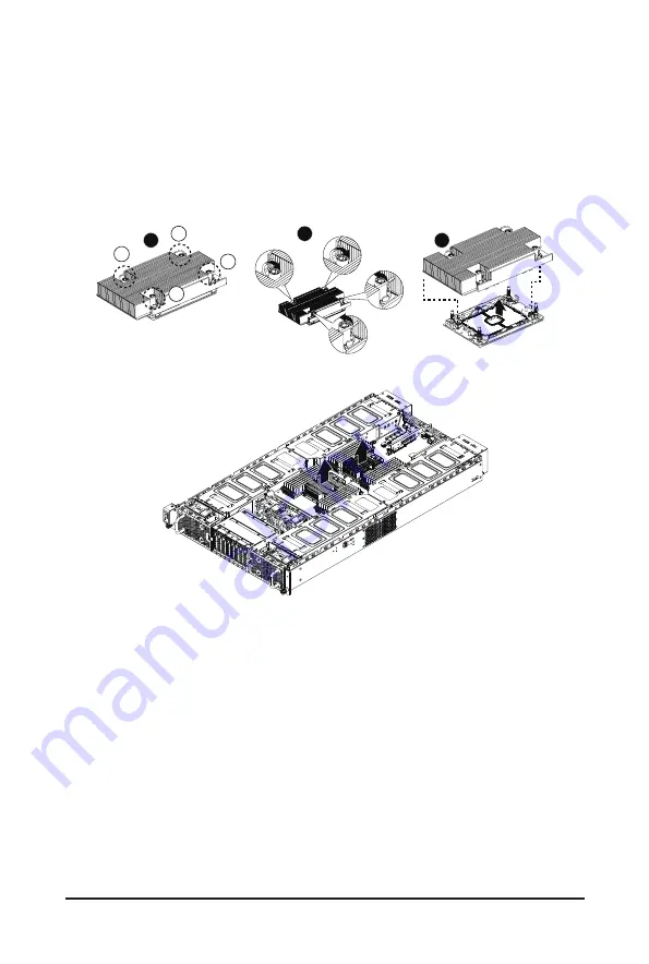
Follow these instructions to remove/install the heat sink:
1. Loosen the captive screws securing the heat sink in place in reverse order (4
g
3
g
2
g
1).
2. Move the rotating wires into the unlatch position.
3. Lift and remove the heat sink from the system.
4. To reinstall the heat sink reverse steps 1-3 while ensuring that you tighten the captive screws in
sequential order (1
g
2
g
3
g
4) as seen in the image below.
3
1
2
3
4
1
2
• When installing the heat sink to CPU, use T30-Lobe driver to tighten 4 captive nuts in sequence
as 1-4.
• The screw tightening torque: 8 ± 0.5 kgf-cm.
Front
Rear
Boom: Slot4 (PCIE_1_PCIE_1)
Top: Slot1 (PCIE_1_PCIE_4)
Boom: Slot16 (PCIE_4_PCIE_1)
Top: Slot13 (PCIE_4_PCIE_4)
Slot14 (PCIE_4_PCIE_3)
Slot15 (PCIE_4_PCIE_2)
Slot2 (PCIE_1_PCIE_3)
Slot3 (PCIE_1_PCIE_2)
Содержание G293-S40
Страница 9: ... 9 5 8 2 DXE Beep Codes 118 ...
Страница 15: ... 15 Hardware Installation 1 3 System Block Diagram 1 3 1 G293 S40 ...
Страница 16: ... 16 Hardware Installation 1 3 2 G293 S41 ...
Страница 31: ... 31 System Hardware Installation For Slot7 Slot8 1 1 2 2 For Slot1 Slot2 1 2 2 1 ...
Страница 32: ... 32 System Hardware Installation 4 3 ...
Страница 34: ... 34 System Hardware Installation For Slot3 Slot4 1 2 2 1 3 4 ...
Страница 36: ... 36 System Hardware Installation For Slot1 Slot2 Slot3 Slot4 1 2 2 1 4 3 ...
Страница 38: ... 38 System Hardware Installation For Slot5 Slot6 Slot7 Slot8 1 2 2 1 3 4 ...
Страница 40: ... 40 System Hardware Installation 3 4 5 6 6 ...
Страница 42: ... 42 System Hardware Installation 5 6 ...
Страница 68: ... 68 BIOS Setup 5 2 4 PCI Subsystem Settings ...
Страница 77: ... 77 BIOS Setup 5 2 12 Intel R X710 Ethernet Network Connection ...
Страница 82: ... 82 BIOS Setup 5 3 1 Processor Configuration ...


