background image

- 85 -

BIOS Setup

5-2-16 

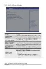
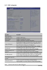
iSCSI Configuration

Parameter

Description

iSCSI Initiator Name

Press [Enter] and name iSCSI Initiator. Only IQN format is accecpted.
Range: from 4 to 223

Add Attempt

Press [Enter] for configuration of advanced items.

Delete Attempt

Press [Enter] for configuration of advanced items.

Change Attempt Order

Press [Enter] for configuration of advanced items.

Содержание G292-Z44

Страница 1: ...G292 Z44 HPC Server 2U DP 8 x Gen4 GPU Server Broadcom solution User Manual Rev 1 0 ...

Страница 2: ...detailed information about the installation use of an add on hardware or software component e g BMC firmware rail kit compatible with this product Quick Installation Guide a short guide with visual diagrams that you can reference easily for installation purposes of this product e g motherboard server barebones Please see the support section of the online product page to check the current availabil...

Страница 3: ...guide NOTE Gives bits and pieces of additional information related to the current topic CAUTION Gives precautionary measures to avoid possible hardware or software problems WARNING Alerts you to any damage that might result from doing or not doing specific actions ...

Страница 4: ...ticular attention to the plug electrical outlet and the point where the cord extends from the server WARNING To reduce the risk of personal injury from hot surfaces allow the drives and the internal system components to cool before touching them WARNING This server is equipped with high speed fans Keep away from hazardous moving fan blades during servicing CAUTION Do not operate the server for lon...

Страница 5: ...scharge ESD and ESD protection ESD can damage drives boards and other parts We recommend that you perform all procedures in this chapter only at an ESD workstation If one is not available provide some ESD protection by wearing an antistatic wrist strap attached to chassis ground any unpainted metal surface on the server when handling parts ESD and handling boards Always handle boards carefully The...

Страница 6: ...on if battery is replaced incorrectly or with an incorrect type Replace the battery only with the same or equivalent type recommended by the manufacturer Dispose of used bat teries according to the manufacturer s instructions ...

Страница 7: ... the Fan Duct 25 3 3 Installing the CPU and Heat Sink 26 3 4 Installing the Memory 28 3 4 1 Eight Channel Memory Configuration 28 3 4 2 Installing a Memory 29 3 4 3 DIMM Population Table 29 3 5 Installing the GPU Card 31 3 6 Installing a PCI Express Card 36 3 7 Installing the Hard Disk Drive 40 3 8 Replacing the FAN Assembly 42 3 9 Replacing the Power Supply 46 3 10 Cable Routing 47 Chapter 4 Moth...

Страница 8: ...v4 Network Configuration 91 5 2 21 MAC IPv6 Network Configuration 92 5 2 22 Intel R Ethernet Controller X550 93 5 3 AMD CBS Menu 95 5 3 1 CPU Common Options 96 5 3 2 DF Common Options 98 5 3 3 UMC Common Options 101 5 3 4 NBIO Common Options 104 5 3 5 FCH Common Options 109 5 3 6 NTB Common Options 112 5 3 7 SOC Miscellaneous Control 113 5 4 AMD PBS Option Menu 114 5 4 1 RAS 115 5 5 Chipset Setup ...

Страница 9: ...s 140 5 10 10 ABL0 test points 140 5 10 11 ABL5 test points 140 5 11 Agesa POST Codes 144 5 11 1 Universal Post Code 144 5 11 2 0xA1XX For CZ only memory Postcodes 144 5 11 3 S3 Interface Post Code 147 5 11 4 PMU Post Code 147 5 11 5 0xA5XX assigned for AGESA PSP Module 147 5 11 6 0xA9XX 0xAAXX assigned for AGESA NBIO Module 150 5 11 7 0xACXX assigned for AGESA CCX Module 152 5 11 8 0xADXX assigne...

Страница 10: ... 10 This page intentionally left blank ...

Страница 11: ...s dry and first touch a metal object to eliminate static electricity Prior to installing the motherboard please have it on top of an antistatic pad or within an electrostatic shielding container Before unplugging the power supply cable from the motherboard make sure the power supply has been turned off Before turning on the power make sure the power supply voltage has been set according to the loc...

Страница 12: ... LRDIMM modules up to 128GB supported Memory speed Up to 3200 MHz LAN 2 x 10Gb s BASE T LAN ports Intel X550 AT2 controller 1 x 10 100 1000 management LAN Video Integrated in Aspeed AST2500 2D Video Graphic Adapter with PCIe bus interface 1920x1200 60Hz 32bpp DDR4 SDRAM Storage 8 x 2 5 hot swappable HDD SSD bays 4 x amber HDD trays compatible with Gen3 U 2 or SATA SAS devices 4 x blue HDD trays co...

Страница 13: ...L please contact your GIGABYTE representative Internal I O 1 x TPM header Front I O 1 x Power button with LED 1 x ID button with LED 2 x LAN activity LEDs 1 x HDD activity LED 1 x System status LED 1 x Reset button Rear I O 2 x USB 3 0 1 x VGA 2 x RJ45 1 x Management LAN 1 x Power button with LED 1 x ID button with LED 1 x Reset button 1 x NMI button 1 x System status LED Backplane I O 8 x SAS SAT...

Страница 14: ... Over LAN HTML5 KVM Sensor Monitor Voltage RPM Temperature CPU Status etc Sensor Reading History Data FRU Information SEL Log in Linear Storage Circular Storage Policy Hardware Inventory Fan Profile System Firewall Power Consumption Power Control LDAP AD RADIUS Support Backup Restore Configuration Remote BIOS BMC CPLD Update Event Log Filter User Management Media Redirection Settings PAM Order Set...

Страница 15: ...er Card 2 x PCIe x16 slots GPU PCIe switch Broadcom Riser Card PCIe4 0 x16 PCIe4 0 x16 2 x PCIe x16 slots GPU PCIe switch Broadcom Riser Card 2 x PCIe x16 slots GPU PCIe switch Broadcom Riser Card PCIe3 0 x1 2 x 10GbE BASE T LAN 2 x USB 3 0 MLAN VGA LPC PCIe2 0 x1 2 x USB2 0 ASPEED AST2500 10 100 1G PHY 1ch MAC BMC PCIe3 0 x4 Intel X550 AT2 8 x SATAIII PCIe4 0 x8 PCIe4 0 x8 8 bay 2 5 SATA with 4 b...

Страница 16: ...Hardware Installation 16 This page intentionally left blank ...

Страница 17: ...nce 2 1 Front View Go to the section 2 3 Front Panel Buttons and LEDs for detail description of function LEDs No Description 1 Front Panel LED and Buttons 2 GPU Fan GPU78_FAN 3 GPU Fan GPU56_FAN HDD 0 HDD 1 HDD 2 HDD 3 HDD 4 HDD 5 HDD 6 HDD 7 1 2 3 ...

Страница 18: ...E_FAN 2 VGA Port 3 10 100 1000 Server Management LAN port 4 Power Button with LED 5 ID Button 6 Reset Button 7 System Status LED 8 LAN Port 2 Active Link LED 9 10G LAN Port x 2 10 LAN Port 1 Active Link LED 11 USB 3 0 Port x 2 12 System Fan GPU56E_FAN 13 Power Supply PSU2 14 NMI Button 15 Power Supply PSU1 ...

Страница 19: ...en On Indicates system is operating normally Amber On Indicates a critical condition may include System fan failure System temperature Blink Indicates non critical condition may include Redundant power module failure Temperature and voltage issue Chassis intrusion N A Off Indicates system is not ready may include POST error NMI error Processor or terminator is missing 5 Reset Button Press this but...

Страница 20: ...m and network or no access Blink Data transmission or reception is occurring N A Off No data transmission or reception is occurring 3 10GbE Speed LED Yellow On 10 Gbps data rate Green On 1000 Mbps data rate N A Off 100 Mbps data rate 4 10GbE Link Activity LED Green On Link between system and network or no access Blink Data transmission or reception is occurring N A Off No data transmission or rece...

Страница 21: ...en Blinking 2Hz Power supply firmware update Amber On AC cord unplugged AC power lost but a second power supply in parallel still having AC input power Power supply critical events that cause a shutdown such as OTP OCP UVP OVP and fan failure Amber Blinking 0 5Hz Power supply warning events where the power supply continues to operate such as high temperature high power high current slot fan PSU LE...

Страница 22: ...tion via HW RAID Card or SW RAID Card Disk LED LED on Back Panel Amber Removed HDD Slot LED on Back Panel Disk LED Removed HDD Slot Green ON 1 OFF Green OFF ON OFF ON 1 OFF OFF ON OFF ON Alternately Low Speed 2 Hz 3 3 OFF OFF Green Amber Green ON 1 OFF Green Green OFF OFF Amber Amber Amber OFF OFF Amber OFF LED 2 HDD Present No HDD Green ON OFF LED 1 LED 2 Reserved ...

Страница 23: ...ver you are working inside the computer case If possible wear a grounded wrist strap when you are working inside the computer case Alternatively discharge any static electricity by touching the bare metal system of the computer case or the bare metal body of any other grounded appliance Hold electronic circuit boards by the edges only Do not touch the components on the board unless it is necessary...

Страница 24: ...e or install the system cover Make sure the system is not turned on or connected to AC power Follow these instructions to remove the system cover 1 Remove the eight screws securing the cover 2 Slide the cover towards the rear and remove the cover in the direction of the arrow ...

Страница 25: ... instructions to remove install the fan duct 1 Lift up to remove the fan duct 2 To install the fan duct align the tabs at the front of the fan duct with the slots in the system fan compartment as shown in the image below and then push down the fan duct into chassis until its firmly seats ...

Страница 26: ...urface Open the system according to the instructions WARNING Failure to turn off the server before you start installing components may cause serious damage Do not attempt the procedures described in the following sections unless you are a qualified service technician Follow these instructions to install the heatsink 1 Loosen the four captive screws securing the heat sink in place in reverse the or...

Страница 27: ... 27 System Hardware Installation 2 3 1 4 CPU0 CPU1 ...

Страница 28: ...IMM_P0_A0 DIMM_P0_E0 DIMM_P0_F0 DIMM_P0_G0 DIMM_P0_H0 DIMM_P1_P0 DIMM_P1_O0 DIMM_P1_N0 DIMM_P1_M0 DIMM_P1_I0 DIMM_P1_J0 DIMM_P1_K0 DIMM_P1_L0 Read the following guidelines before you begin to install the memory Make sure that the motherboard supports the memory It is recommended that memory of the same capacity brand speed and chips be used Always turn off the computer and unplug the power cord fr...

Страница 29: ...the plastic clip at both edges of the DIMM slots to lock the DIMM module 3 Reverse the installation steps when you want to remove the DIMM module 1 2 2 3 4 3 DIMM Population Table Be sure to install DDR4 DIMMs on this motherboard The initial DIMMs installed must be installed in the primary CPU CPU0 memory slots first Install the memory in alphabetic order starting with Bank A If the system feature...

Страница 30: ...rted 1 2 DIMMs Populated DIMM 2S2R 2S4R 1 2 2933 2666 1 2V Frequency MT s LRDIMM Maximum Frequency Supported 4DR 2 1 DIMMs Populated DIMM 2S2R 2S4R 1 1 2 2 1 1 3200 3200 2933 Not Supported 2933 1 2V Frequency MT s 1R 1 package rank of SDP DRAMs 2R 2 package rank of SDP DRAMs 2DR 2 package rank of DDP DRAMs 4DR 4 package rank of DDP DRAMs 2S2R 2S4R 2S8R 2 package rank of 2 4 8 high 3DS DRAMs ...

Страница 31: ... any cabling as standard To install a PCI card a riser card must be installed For GPU1 GPU2 GPU7 GPU8 Follow these instructions to install the GPU card 1 For GPU7 GPU8 Loosen and remove the two screws securing the PCI cage at the top of the system For GPU1 GPU2 Loosen and remove the single screw at the top of the system and the two screws at the rear of the system securing the PCI cage 2 Pull the ...

Страница 32: ...System Hardware Installation 32 For GPU7 GPU8 1 2 2 For GPU1 GPU2 Front Rear 1 ...

Страница 33: ... 33 System Hardware Installation 1 2 2 3 4 ...

Страница 34: ...ingle screw at the top of the system and the two screws at the rear of the system securing the PCI cage Pull the two plastic handles to lift up the PCI cage from the system 2 Insert the card into the selected slot Make sure that the card is properly seated 3 Secure the GPU cards in place with two screws Front Rear Top GPU4 PCIE_3_PCIE_2 Bottom GPU3 PCIE_3_PCIE_1 Top GPU6 PCIE_2_PCIE_2 Bottom GPU5 ...

Страница 35: ... 35 System Hardware Installation 1 1 2 2 For GPU3 GPU4 1 1 2 2 3 4 ...

Страница 36: ...e to equipment Follow these instructions to install a PCI Express x8 card on right side of the system 1 Loosen and remove the two screws securing the PCI Express card bracket on the right side of the system 2 Remove the PCI Express card bracket from the system 3 Install the PCI Express card into the bracket 4 Secure the PCI Express card to the bracket with one screw 5 Install the PCI Express card ...

Страница 37: ... 37 System Hardware Installation 3 4 5 6 6 ...

Страница 38: ...the PCI Express card bracket from the system 3 Install the PCI Express card into the bracket 4 Secure the PCI Express card to the bracket with one screw 5 Install the PCI Express card bracket with card back into the system ensure that the connector on the bracket is securely installed into the connector on the motherboard as shown 6 Secure the PCI Express card bracket with card to the system using...

Страница 39: ... 39 System Hardware Installation 5 6 ...

Страница 40: ...disk drive 1 Press the release button 2 Extend the locking lever 3 Pull the locking lever to remove the HDD tray 4 Slide the hard disk drive into the blank HDD tray 5 Secure the hard drive to the tray with four 4 screws as shown Do not over tighten the screws Slide the hard drive tray into the bay until it locks in place CAUTION We strongly recommend using enterprise level hard disk drives in the ...

Страница 41: ... 41 System Hardware Installation ...

Страница 42: ... connections Failure to observe these warnings could result in personal injury or damage to the equipment GPU56E_FAN GPU12E_FAN GPU12_FAN GPU56_FAN SYS_FAN2 SYS_FAN1 GPU78_FAN GPU34_FAN Follow these instructions to replace the fan assembly For GPU12_FAN GPU24_FAN GPU56_FAN GPU78_FAN 1 Disconnect the fan cable and then lift up the fan assembly from the chassis 2 Reverse the previous steps to instal...

Страница 43: ...nstallation 2 Airflow direction 2 Airflow direction For SYS_FAN1 SYS_FAN2 1 Disconnect the fan cable and then lift up the fan assembly from the chassis 2 Reverse the previous steps to install the replacement fan assembly 1 ...

Страница 44: ... direction For GPU12E_FAN GPU56E_FAN 1 Disconnect the fan cable and then loosen and remove the screws securing the fan cage 2 Remove the fan cage from the system 3 Reverse the previous steps to install the replacement fan assembly 1 1 2 2 1 1 ...

Страница 45: ... 45 System Hardware Installation 4 4 3 3 4 4 Airflow direction CAUTION To avoid fan cable damage please make sure the fan cables are firmly seated in the cable routing hooks ...

Страница 46: ...he arrow 2 At the same time pull out the power supply using the handle 3 Insert the replacement power supply firmly into the chassis Connect the AC power cord to the replacement power supply 1 2 3 CAUTION Please see the illustration below for installation sequence Primary PSU PSU1 Secondary PSU PSU2 CAUTION In order to reduce the risk of injury from electric shock disconnect AC power from the powe...

Страница 47: ... 47 System Hardware Installation 3 10 Cable Routing System Main Power MB Top Tray Connector System Fan Power ...

Страница 48: ...System Hardware Installation 48 CPU Power MB Top Tray Connector 1 x 3 Power ...

Страница 49: ... 49 System Hardware Installation HDD Backplane Board Signal HDD Backplane Board Power ...

Страница 50: ...System Hardware Installation 50 Power Distribution Board to HDD Backplane Board Power SMD ...

Страница 51: ... 51 System Hardware Installation SlimLine SAS 1 MB Top Tray Connector SlimLine SAS 2 MB Top Tray Connector ...

Страница 52: ...System Hardware Installation 52 Front Panel IO NVMe ...

Страница 53: ... 53 System Hardware Installation NVMe Bo om Connector ...

Страница 54: ...System Hardware Installation 54 NVMe Bo om Connector ...

Страница 55: ...e 4i Connector 3 U2_P1_P0_1 support NVMe 19 SlimLine 4i Connector 3 U2_P1_P0_0 support NVMe 20 SlimLine 4i Connector 4 SL_SATA4 21 SlimLine 4i Connector 3 SL_SATA3 22 2 x 9 Pin CPU Power Connector for CPU1 23 Front Panel Header secondary for power distribution board 24 PCIe x16 Slot 3 25 SlimLine 4i Connector x 8 U2_P1_G1_7 4 U2_P0_G3_3 0 Right to Left 26 PCIe x16 Slot 1 27 Related System Voltage ...

Страница 56: ...Motherboard Components 56 30 System Battery Cable Connector 31 Mezzanine Slot 32 TPM Connector 33 BMC Readiness LED 34 NCSI Cable Connector ...

Страница 57: ...Clear CMOS CLR_CMOS1 Default Enable 1 2 3 NCSI Switch 21 Onboard LAN Mezzanine Slot ON OFF HOST_SMBUS_SEL PMBUS_SEL ON BIOS recovery mode Normal Default Normal Default BIOS defined BIOS defined Clear supervisor password OFF BIOS_PWD BIOS ROCOVERY J1 1 2 3 4 ...

Страница 58: ...Motherboard Components 58 This page intentionally left blank ...

Страница 59: ... caution Inadequate BIOS flashing may result in system malfunction It is recommended that you not alter the default settings unless you need to to prevent system instability or other unexpected results Inadequately altering the settings may result in system s failure to boot If this occurs try to clear the CMOS values and reset the board to default values Refer to the Exit section in this chapter ...

Страница 60: ... Bridge South Bridge and System event logs Server Management Server additional features enabled disabled setup menus Security Change set or disable supervisor and user password Configuration supervisor password allows you to restrict access to the system and BIOS Setup A supervisor password allows you to make changes in BIOS Setup A user password only allows you to view the BIOS settings but not t...

Страница 61: ... displayed on the bottom line of the Main Menu Submenu Help While in a submenu press F1 to display a help screen General Help of function keys available for the menu Press Esc to exit the help screen Help for each item is in the Item Help block on the right side of the submenu When the system is not stable as usual select the Restore Defaults item to set your system to its defaults The BIOS Setup ...

Страница 62: ...on number of the BIOS setup utility BIOS Information Project Name Displays the project name information Project Version Displays version number of the BIOS setup utility Build Date and Time Displays the date and time when the BIOS setup utility was created BMC Information BMC Firmware Version Displays version number of the BIOS setup utility Processor Information CPU 0 Brand String CPU 1 Brand Str...

Страница 63: ...ion information Onboard LAN Information LAN1 MAC Address Note2 Displays LAN MAC address information LAN2 MAC Address Note2 Displays LAN MAC address information System Date Sets the date following the weekday month day year format System Time Sets the system time following the hour minute second format Note1 This section will display capacity and frequency information of the memory that the custome...

Страница 64: ... Setup 64 5 2 Advanced Menu The Advanced menu display submenu options for configuring the function of various hardware components Select a submenu item then press Enter to access the related submenu screen ...

Страница 65: ...figuration Security Device Support Select Enable to activate TPM support feature Options available Enable Disable Default setting is Enable SPI TPM Support Options available Enabled Disabled Default setting is Enabled 5 2 1 Trusted Computing ...

Страница 66: ...BIOS Setup 66 5 2 2 PSP Firmware Versions The PSP Firmware Versions page displays the basic PSP firmware version information Items on this window are non configurable ...

Страница 67: ...Displays the Redish version supported by BIOS Authentication Mode Press Enter to select the authentication mode Options available Basic Authentication Session Authentication Default setting is Basic Authentication Redish BMC Settings IP Address Press Enter to configure the IP address IP Mask Address Press Enter to configure the IP mask address IP Port Press Enter to configure the IP port ...

Страница 68: ...OnBrd Ext VGA Select Note Select between onboard or external VGA support Options available Auto Onboard External Default setting is Onboard Note This configurable option will be displayed when Boot Mode Select is set to Legacy in the Boot Boot Mode Select section ...

Страница 69: ... 69 BIOS Setup 5 2 5 AST2500 Super IO Configuration Parameter Description AST2500 Super IO Configuration Super IO Chip Displays the super IO chip information ...

Страница 70: ...ngs Change Settings Note2 Select an optimal setting for the Super I O device Options available for Serial Port 1 Auto IO 3F8h IRQ 4 IO 3F8h IRQ 3 4 5 6 7 9 10 11 12 IO 2F8h IRQ 3 4 5 6 7 9 10 11 12 IO 3E8h IRQ 3 4 5 6 7 9 10 11 12 IO 2E8h IRQ 3 4 5 6 7 9 10 11 12 Default setting is Auto Options available for Serial Port 2 Auto IO 2F8h IRQ 3 IO 3F8h IRQ 3 4 5 6 7 9 10 11 12 IO 2F8h IRQ 3 4 5 6 7 9 ...

Страница 71: ... Enable or disable system wake on alarm event Select Fixed Time system will wake on the time HH MM SS specified Select Dynamic Time and the system will wake at the current time plus an increase in minute s Options available Disabled Fixed Time Dynamic Time Default setting is Disabled ...

Страница 72: ...on the available COM ports Serial Port for Out of Band Management Windows Emergency Management Services EMS Console Redirection Note Selects a COM port for EMS console redirection EMS console redirection allows the user to configure Console Redirection Settings to support Out of Band Serial Port management Options available Enabled Disabled Default setting is Disabled COM1 SOL Console Redirection ...

Страница 73: ...th slow devices may require more than 1 stop bit Options available 1 2 Default setting is 1 Flow Control Flow control can prevent data loss from buffer overflow When sending data if the receiving buffers are full a stop signal can be sent to stop the data flow Once the buffers are empty a start signal can be sent to re start the flow Hardware flow control uses two wires to send start stop signals ...

Страница 74: ... Console Redirection Settings Out of Band Mgmt Port Selects a serial port to remotely manage a Windows server OS Options available COM1 SOL Default setting is COM1 SOL Terminal Type Selects a terminal type to be used for console redirection Options available VT100 VT100 ANSI VT UTF8 Default setting is VT UTF8 Bits per second Selects the transfer rate for console redirection Options available 9600 ...

Страница 75: ...tions available Enabled Disabled Default setting is Enabled SMEE Controls the Secure Memory Encryption Enable SMEE function Options available Enabled Disabled Default setting is Enabled CPU 0 Information Press Enter to view more information related to CPU 0 CPU 1 Information Press Enter to view more information related to CPU 1 ...

Страница 76: ...BIOS Setup 76 5 2 9 AMI Graphic Output Protocol Policy Parameter Description ASPEED Graphics PCI Adapter ASPEED Graphics Driver Output Select Press Enter to select output interface ...

Страница 77: ...n ROM for the related PCI E slot Options available Enabled Disabled Default setting is Enabled Onboard LAN 1 Controller Note2 Enable Disable the onboard LAN devices Options available Enabled Disabled Default setting is Enabled Onboard LAN 1 I O ROM Note2 Enable Disable the onboard LAN devices and initializes device expansion ROM Options available Enabled Disabled Default setting is Enabled PCI Dev...

Страница 78: ...m has SR IOV capable PCIe devices this item Enable Disable Single Root IO Virtualization Support Options available Enabled Disabled Default setting is Enabled PCI E AER Enabled Enable Disable PCI E AER Options available Enabled Disabled Default setting is Disabled ...

Страница 79: ...ff Enable Disable the XHCI USB 3 0 Hand off support Options available Enabled Disabled Default setting is Enabled USB Mass Storage Driver Support Note Enable Disable the USB Mass Storage Driver Support Options available Enabled Disabled Default setting is Enabled Port 60 64 Emulation Enables the I O port 60h 64h emulation support This should be enabled for the complete USB Keyboard Legacy support ...

Страница 80: ...or a Root port it is 100 ms for a Hub port the delay is taken from Hub descriptor Options available Auto Manual Default setting is Auto Mass Storage Devices AMI Virtual CDROM0 1 00 AMI HDisk0 1 00 Generic Flash Disk 8 07 ADATA USB Flash Drive 1100 Mass storage device emulation type AUTO enumerates devices according to their media format Optical drives are emulated as CDROM drives with no media wil...

Страница 81: ... 81 BIOS Setup 5 2 12 NVMe Configuration Parameter Description NVMe controller and Drive Information Displays the NVMe devices connected to the system ...

Страница 82: ...BIOS Setup 82 5 2 13 SATA Configuration ...

Страница 83: ...setting is Disabled Ipv6 PXE Support Note Enable Disable the Ipv6 PXE feature Options available Enabled Disabled Default setting is Disabled Ipv6 HTTP Support Note Enable Disable the Ipv6 HTTP feature Options available Enabled Disabled Default setting is Disabled IPSEC Certificate Note Enable Disable the IPSEC Certificate feature Options available Enabled Disabled Default setting is Enabled PXE bo...

Страница 84: ...anced items Channel A BC D E F G H DIMM0 Presence DIMM1 Presence Chipset Bank Interleave Dram EC Dram Parity Dimm Sensor Fine Grain Mode CPU 1 Press Enter for configuration of advanced items Channel I J K L M N O P DIMM0 Presence DIMM1 Presence Chipset Bank Interleave Dram EC Dram Parity Dimm Sensor Fine Grain Mode ...

Страница 85: ...Name Press Enter and name iSCSI Initiator Only IQN format is accecpted Range from 4 to 223 Add Attempt Press Enter for configuration of advanced items Delete Attempt Press Enter for configuration of advanced items Change Attempt Order Press Enter for configuration of advanced items ...

Страница 86: ...n Press Enter for configuration of advanced items Enroll Cert Press Enter to enroll a certificate Enroll Cert Using File Cert GUID Input digit character in 1111111 2222 3333 4444 1234567890ab format Commit Changes and Exit Discard Changes and Exit Delete Cert Client Cert Configuration N A ...

Страница 87: ... 87 BIOS Setup 5 2 18 Intel R I350 Gigabit Network Connection ...

Страница 88: ... Press the numeric keys to adjust desired values UEFI Driver Displays the technical specifications for the Network Interface Controller Adapter PBA Displays the technical specifications for the Network Interface Controller Device Name Displays the technical specifications for the Network Interface Controller Chip Type Displays the technical specifications for the Network Interface Controller PCI D...

Страница 89: ... 89 BIOS Setup 5 2 19 VLAN Configuration ...

Страница 90: ... to 4094 Priority Sets 802 1Q Priority for a new VLAN or an existing VLAN Press the keys to increase or decrease the desired values The valid range is from 0 to 7 Add VLAN Press Enter to create a new VLAN or update an existing VLAN Configured VLAN List Note Enable Disable the VLAN Options available Enable Disable Default setting is Disabled Remove VLAN Press Enter to remove an existing VLAN Note O...

Страница 91: ...e Enabled Disabled Default setting is Enabled Local IP Address Note Press Enter to configure local IP address Local NetMask Note Press Enter to configure local NetMask Local Gateway Note Press Enter to configure local Gateway Local DNS Servers Note Press Enter to configure local DNS servers Save Changes and Exit Press Enter and then choose to save or discard the changes made Note This item will ap...

Страница 92: ...e Table Gateway addresses DNS addresses Interface ID The 64 bit alternative interface ID for the device The string is colon separated e g ff dd 88 66 cc 1 2 3 DAD Transmit Count The number of consecutive Neighbor Solicitaion messages sent while performing Duplicate Address Detection on a tentative address A value of zero indicates that Duplicate Addres Detection is not performed Policy Save Change...

Страница 93: ... 93 BIOS Setup 5 2 22 Intel R Ethernet Controller X550 ...

Страница 94: ... Press the numeric keys to adjust desired values UEFI Driver Displays the technical specifications for the Network Interface Controller Adapter PBA Displays the technical specifications for the Network Interface Controller Device Name Displays the technical specifications for the Network Interface Controller Chip Type Displays the technical specifications for the Network Interface Controller PCI D...

Страница 95: ...etup 5 3 AMD CBS Menu AMD CBS menu displays submenu options for configuring the CPU related information that the BIOS automatically sets Select a submenu item then press Enter to access the related submenu screen ...

Страница 96: ...f CCDs to be used the number of cores to be used and whether to enable or disable symmetric multithreading Prefetcher settings Press Enter for more options L1 Stream HW Prefetcher Option to enable or disable L1 Stream HW Prefetcher Options available Disable Enable Auto Default option is Auto L2 Stream HW Prefetcher Option to enable or disable L2 Stream HW Prefetcher Options available Disable Enabl...

Страница 97: ...3 ASIDs 509 ASIDs Auto Default option is Auto SEV ES ASID Space Limit Control Space limit control for SEV ES ASIDs Options available Auto Manual Default option is Auto Streaming Stores Control Enables or disables the streaming stores functionality Options available Disabled Enabled Auto Default option is Auto Local APIC Mode Sets the Local APIC mode Options available xAPIC x2APIC Auto Default opti...

Страница 98: ...l Allows you to enable or disable poison scrubber control Options available Disabled Enabled Auto Default option is Auto Redirect scrubber control Allows you to enable or disable redirect of scrubber control Options available Disabled Enabled Auto Default option is Auto Redirect scrubber limit Allows you to set the redirect scrubber limit Options available 2 4 8 Infinite Auto Default option is Aut...

Страница 99: ...to remap DRAM out of the space just below the 1TB boundary The ability to remap depends on DRAM configuration NPS and interleaving selection and may not always be possible Options available Do not remap Attempt to remap Auto Default option is Auto DRAM map inversion Inverting the map will cause the highest memory channels to get assigned the lowest addresses in the system Options available Disable...

Страница 100: ...et Auto Default option is Auto Disable DF to external IP Sync Flood Propagation Disable SyncFlood to UMC downstream slaves Options avaialble Sync flood disabled Sync flood enabled Auto Default option is Auto Disable DF sync flood propagation Enable Disable DF SyncFlood Options avaialble Sync flood disabled Sync flood enabled Auto Default option is Auto Freeze DF module queues on error Controls DF ...

Страница 101: ...ill be capped at AMD guidelines To enable 2 DIMMS per Channel at 3200MHz function select Accept at warning message switch Overclock from Auto to Enabled and then set memory speed to 3200Mhz DRAM Controller Configuration Press Enter to configure DRAM controller options DRAM Power Options Cmd2T Gear Down Mode CAD Bus Configuration Press Enter to configure CAD Bus options CAD Bus Timing User Controls...

Страница 102: ...hat alters how applications get assigned to physical locations within the memory modules When this option sets to Auto it is null Options available Enabled Disabled Auto Default option is Auto BankGroupSwapAlt Configures the BankGroupSwapAlt Options available Enabled Disabled Auto Default option is Auto Address Hash Bank Enable or disable bank address hashing Options available Disabled Enabled Aut...

Страница 103: ...atic Lane Control Aggressor Static Lane Select Upper 32 bits Aggressor Static Lane Select Lower 32 bits Aggressor Static Lane Select ECC Aggressor Static Lane Value Target Static Lane Control Target Static Lane Select Upper 32 bits Target Static Lane Select Lower 32 bits Target Static Lane Select ECC Target Static Lane Value Data Eye Type Worst Case Margin Granularity Read Voltage Sweep Step Size ...

Страница 104: ...Ie ARI Support Enables Alternative Routing ID Interpretation Options available Disable Enable Auto Default option is Auto PCIe Ten Bit Tag Support Enables PCIe ten bit tags for supported devices Auto Disabled Options available Disable Enable Auto Default option is Auto HD Audio Enable Enables or disables HD Audio Options available Enable Disabled Auto Default option is Auto ...

Страница 105: ...power efficiency optimized CCLK DPM settings Options available Auto Enabled Default option is Auto Package Power Limit Control Auto Use the fused PPT Manual User can set PPT PPT will be used as the ASIC power limit Options available Manual Auto Default option is Manual xGMI Link Width Control Auto Use degault xGMI link width controller Manual User can set custom xGMI link width controller settings...

Страница 106: ...d to APML When set to FALSE that reporting will be disabled Options available Enabled Disabled Default option is Disabled Egress Poison Mask High Enter a value These set the enable mask for masking of errors logged in EGRESS_POISON_STATUS For each bit set to 1 errors are masked For each bit set to 0 errors trigger response actions Egress Poison Mask Low Enter a value These set the enable mask for ...

Страница 107: ...erted to Okay responses Options available Enabled Trigger MCOMMIT Error Log Errors in MCA Default option is Log Errors in MCA Log Poison Data from SLINK This value specifies whether poison data propogated from SLINK will generate a deferred error When this value is set to TRUE deferred errors are enabled When set to FALSE errors are not generated Options available Enabled Disabled Default option i...

Страница 108: ...o Enable AER Cap Enables Advanced Error Reporting Capabilty Options available Enable Disabled Auto Default option is Auto Early Link Speed Sets Early Link Speed Options available Auto Gen1 Gen2 Default option is Auto Hot Plug Handling mode Controls the Hot Plug Handling mode Options available A0 Mode OS First No Error Handling OS First Error Handling Not Implementd Firmware First Not Implemented A...

Страница 109: ... Sata Disabled AHCI Prefetch Function Enable or disable Sata Disabled AHCI Prefetch Function Options available Disabled Enabled Auto Default setting is Auto Aggressive SATA Device Sleep Port 0 Options available Disabled Enabled Auto Default setting is Auto Aggressive SATA Device Sleep Port 1 Options available Disabled Enabled Auto Default setting is Auto SATA Controller options Press Enter for mor...

Страница 110: ...if Uart 3 is enabled Options available Disabled Enabled Auto Default setting is Auto Uart 2 Enable no HW FC Options available Disabled Enabled Auto Default setting is Auto Uart 3 Enable no HW FC Options available Disabled Enabled Auto Default setting is Auto ESPI Configuration Options Press Enter for more options ESPI Enable Options available Disabled Enabled Auto Default setting is Auto eMMC Opti...

Страница 111: ...nter for more options ALink RAS Support Options available Disabled Enabled Auto Default setting is Auto Reset after sync flood Enable AB to forward downstream sync flood message to system controller Options available Disabled Enabled Auto Default setting is Auto ...

Страница 112: ...BIOS Setup 112 5 3 6 NTB Common Options Parameter Description NTB Common Options NTB Enable Enable or disable OnChip SATA controller Options available Auto Enable Default setting is Auto ...

Страница 113: ...able Auto Default setting is Auto ABL Basic Console Out Control Enable Enable Basic ConsoleOut Function for ABL Disable Disable Basic ConsoleOut Function for ABL Auto Keep default behavior Options available Disable Enable Auto Default setting is Auto ABL PMU message Control Controls the total number of PMU debug message Options available Detailed debug message Coarse debug message Stage completion...

Страница 114: ...g the function of AMD PBS Select a submenu item then press Enter to access the related submenu screen Parameter Description AMD PBS RAS Press Enter for advanced configurations SPI Locking Enable or disable SPI Locking for protect ROM part Options Available Enabled Disabled Default option is Disabled ...

Страница 115: ...ue is 1000 dec SMI Scale Unit Defines the unit of time scale Options available millisecond second minute Default option is millisecond SMI Period Enter a value Defines the polling interval in milliseconds Default option is 1000 dec Maximum value is 32767 dec 0 disable GHES Notify Type Notification type for deferred corrected errors Options Available Polled SCI Default option is Polled GHES UnCorr ...

Страница 116: ...Device UnCorr Err Mask Reg Enter a value Intialize the PCIe AER Uncorrected Error Mask register of PCIe Device PCIe Device UnCorr Error Sev Reg Enter a value Intialize the PCIe AER Uncorrected Error Severity registers of PCIe Device CCIX GHES Deferred Err Notify Type Notification type for CCIX deferred errors Options Available Polled SCI Default option is Polled CCIX GHES Corrected Err Notify Type...

Страница 117: ...creen Parameter Description PCIe Link Training Type PCIe Link training in 1 or 2 steps Options available 1 Step 2Step Default setting is 1 Step PCIe Compliance Mode Options available On Off Default setting is Off Program All VR Enables or disables program all VR on MB Options available Disabled Enabled Default setting is Enabled North Bridge Press Enter for more information related to CPU 0 and CP...

Страница 118: ...s set to Enabled OS Watchdog Timer Enable Disable OS Watchdog Timer function Options available Enabled Disabled Default setting is Disabled OS Wtd Timer Timeout Configure OS Watchdog Timer Options available 5 minutes 10 minutes 15 minutes 20 minutes Default setting is 10 minutes NOTE This item is configurable when OS Watchdog Timer is set to Enabled OS Wtd Timer Policy Configure OS Watchdog Timer ...

Страница 119: ...Event Log Press Enter to configure advanced items View FRU Information Press Enter to view the FRU information BMC network configuration Press Enter to configure advanced items IPv6 BMC Network Configuration Press Enter to configure advanced items ...

Страница 120: ...sing SEL Choose options for erasing SEL Options available No Yes On next reset Yes On every reset Default setting is No When SEL is Full Choose options for reactions to a full SEL Options available Do Nothing Erase Immediately Default setting is Do Nothing Custom EFI Logging Options Log EFI Status Codes Enable Disable the logging of EFI Status Codes if not already converted to legacy Options avail...

Страница 121: ...nformation The FRU page is a simple display page for basic system ID information as well as System product information Items on this window are non configurable Note The model name will vary depending on the product you have purchased ...

Страница 122: ...BMC network parameters during BIOS phase Options available Unspecified Static DynamicBmcDhcp Default setting is DynamicBmcDhcp Station IP address Displays IP Address information Subnet mask Displays Subnet Mask information Router IP address Displays the Router IP Address information Station MAC address Displays the MAC Address information Real time synchronize BMC network parameter values Press En...

Страница 123: ...C network during BIOS phase Options available Unspecified Disable Enable Default setting is Enable IPv6 BMC Lan IP Address Source Select to configure LAN channel parameters statically or dynamically by BIOS or BMC Options available Unspecified Static Dynamic Obtained by BMC running DHCP Default setting is Dynamic Obtained by BMC running DHCP IPv6 BMC Lan IP Address Prefix Length Check if the IPv6 ...

Страница 124: ...ll settings in the Setup Utility User Password Entering this password will restrict a user s access to the Setup menus To enable or disable this field a Administrator Password must first be set A user can only access and modify the System Time System Date and Set User Password fields Parameter Description Administrator Password Press Enter to configure the administrator password User Password Pres...

Страница 125: ...es being loaded before Windows loads and gets to the login screen have not been tampered with When set to Standard it will automatically load the Secure Boot keys form the BIOS databases When set to Custom you can customize the Secure Boot settings and manually load its keys from the BIOS database Options available Standard Custom Default setting is Custom Restore Factory Keys Forces the system to...

Страница 126: ...splays the current status of the Key Exchange Key Database KEK Press Enter to configure a new KEK or load additional KEK from storage devices Options available Set Update Append Authorized Signatures DB Displays the current status of the Authorized Signature Database Press Enter to configure a new DB or load additional DB from storage devices Options available Set Update Append Forbidden Signature...

Страница 127: ...put the desired values Bootup NumLock State Enable Disable the Bootup NumLock function Options available On Off Default setting is On Quiet Boot Enable Disable showing the logo during POST Options available Disabled Enabled Default setting is Enabled Boot mode select Selects the boot mode Options available LEGACY UEFI Default setting is UEFI FIXED BOOT ORDER Priorities Boot Option 1 2 3 4 5 Press ...

Страница 128: ...es Press Enter to configure the boot priority UEFI USB Drive BBS Priorities Press Enter to configure the boot priority UEFI Network Drive BBS Priorities Press Enter to configure the boot priority UEFI Application Boot Priorities Press Enter to configure the boot priority ...

Страница 129: ...rities The UEFI hard disk drive BBS priorities submenu allows you to specify the boot device priority from the available UEFI hard disk drives during system boot up BIOS setup will display an error message if the legacy drive s specified is not bootable ...

Страница 130: ...iorities The UEFI USB drive BBS priorities submenu allows you to specify the boot device priority from the available UEFI USB drives during system boot up BIOS setup will display an error message if the legacy drive s specified is not bootable ...

Страница 131: ...orities The UEFI network drive BBS priorities submenu allows you to specify the boot device priority from the available UEFI network drives during system boot up BIOS setup will display an error message if the legacy drive s specified is not bootable ...

Страница 132: ...orities The UEFI application boot priorities submenu allows you to specify the boot device priority from the available UEFI applications during system boot up BIOS setup will display an error message if the legacy drive s specified is not bootable ...

Страница 133: ... so far to any of the setup options Options available Yes No Default Options Restore Defaults Loads the default settings for all BIOS setup parameters Setup Defaults are quite demanding in terms of resources consumption If you are using low speed memory chips or other kinds of low performance components and you choose to load these settings the system might not function properly Options available ...

Страница 134: ...face 0xE00D ProcMemPhyFenceTraining 0xE00E ProcMemSynchronizeDcts 0xE00F ProcMemSystemMemoryMapping 0xE010 ProcMemMtrrConfiguration 0xE011 ProcMemDramTraining 0xE012 ProcMemBeforeAnyTraining Public interface 0xE013 5 10 3 PMU Test Points ABL Mem PMU Before PMU Firmware load 0xE014 ABL Mem PMU After PMU Firmware load 0xE015 ABL Mem PMU Populate SRAM Timing 0xE016 ABL Mem PMU Populate SRAM Config 0x...

Страница 135: ... ABL Mem Read Test pattern 0xE036 ABL Mem Compare Test pattern 0xE037 ABL Mem Online Spare init 0xE038 ABL Mem Chip select Interleave Init 0xE039 ABL Mem Node Interleave Init 0xE03A ABL Mem Channel Interleave Init 0xE03B ABL Mem ECC initialization 0xE03C ABL Mem Platform Specific Init 0xE03D ABL Mem Before callout for AgesaReadSpd 0xE03E ABL Mem After callout for AgesaReadSpd 0xE03F ABL Mem Before...

Страница 136: ... init 0xE057 Exit point CPU APOB EDC info init 0xE058 5 10 6 Topology test points ProcTopologyEntry 0xE071 ProcTopologyDone 0xE07C 5 10 7 Extended memory test point ProcMemSendMRS2 0xE080 Sedding MRS3 0xE081 Sending MRS1 0xE082 Sending MRS0 0xE083 Continuous Pattern Read 0xE084 Continuous Pattern Write 0xE085 Mem 2d RdDqs Training begin 0xE086 Mem Before optional callout to platform BIOS to change...

Страница 137: ...de 0xE09F TP0xA0 0xE0A0 GNB internal debug code 0xE0A1 GNB internal debug code 0xE0A2 GNB internal debug code 0xE0A3 GNB internal debug code 0xE0A4 GNB internal debug code 0xE0A5 GNB internal debug code 0xE0A6 GNB internal debug code 0xE0A7 GNB internal debug code 0xE0A8 GNB internal debug code 0xE0A9 GNB internal debug code 0xE0AA GNB internal debug code 0xE0AB GNB internal debug code 0xE0AC GNB ...

Страница 138: ...Initialization Stage 4 Warning 0xF4C0 ABL 3 GMI xGMI Initialization Stage 4 Error 0xE5C0 ABL 3 GMI xGMI Initialization Stage 5 0xB5C0 ABL 3 GMI xGMI Initialization Stage 5 Warning 0xF5C0 ABL 3 GMI xGMI Initialization Stage 5 Error 0xE6C0 ABL 3 GMI xGMI Initialization Stage 6 0xB6C0 ABL 3 GMI xGMI Initialization Stage 6 Warning 0xF6C0 ABL 3 GMI xGMI Initialization Stage 6 Error 0xE7C0 ABL 3 GMI xGM...

Страница 139: ...n AP 0xE0E0 Before IDS calls out to get IDS data 0xE0E1 After IDS calls out to get IDS data 0xE0E2 Before the heap manager calls out to allocate a buffer 0xE0E3 After the heap manager calls out to allocate a buffer 0xE0E4 Before the heap manager calls out to deallocate a buffer 0xE0E5 After the heap manager calls out to deallocate a buffer 0xE0E6 Before the heap manager calls out to locate a buffe...

Страница 140: ... Initialization 0xE103 End of phase 1b memory code 0xE104 ABL 1b memory initialization 0xE105 ABL 6 Global memroy error detected 0xE106 ABL 1b Debug Synchronization Function 0xE107 ABL 4b Debug Synchronization Function 0xE108 AblbBegin 0xE109 Ab4bBegin 0xE10A BSP encountered HMAC fail on APOB Header 0xE10B ABL Eroor General ASSERT 0xE2A0 Unknown Error 0xE2A1 ABL Error Log Inig Error 0xE2A2 ABL Err...

Страница 141: ...r DDR Recovery error 0xE2BE ABL Error for RRW Test error 0xE2BF ABL Error for On Die Thermal error 0xE2C1 ABL Error for Heap Allocation For Dct Struct Amd Ch Def structure error 0xE2C2 ABL Error for Heap Allocation for PMU SRAM Msg block error 0xE2C3 ABL Error for Heap Phy PLL lock Flure error 0xE2C4 ABL Error for Pmu Training error 0xE2C5 ABL Error for Failure to Load or Verify PMU FW error 0xE2C...

Страница 142: ... Error 0xE2EB ABL Error MBIST Heap Allocation Error 0xE2EC ABL Error MBIST Results Error 0xE2EE ABL Error NO Dimm Smcus Info Error 0xE2EE ABL Error Por Max Freq Table Error 0xE2EF ABL Error Unsupproted DIMM Config Error 0xE2F0 ABL Error No Ps Table Error 0xE2F1 ABL Error Cad Bus Timing Not Found Error 0xE2F2 ABL Error Data Bus Timing Not Found Error 0xE2F3 ABL Error LrDIMM IBT Not Found Error 0xE2...

Страница 143: ...E30A ABL Error message slave sync function execution Error 0xE30B ABL Error slave offline Error 0xE30C ABL Error Sync Master Error 0xE30D ABL Error Slave Informs Master Info Message Error 0xE30E ABL Error General Assert Error 0xE30F ABL Error No Dimms On Any Channel in sysem 0xE310 ABL Alert PMU Major Message captured 0xE311 ABL Alert PMU REsults Rx Timing captured 0xE312 ABL Alert PMU REsults Tx ...

Страница 144: ...A107 TpProcMemSpdTiming 0xA108 TpProcMemDramMapping 0xA109 TpProcMemPlatformSpecificConfig 0xA10A TPProcMemPhyCompensation 0xA10B TpProcMemStartDcts 0xA10C Public interface 0xA10D TpProcMemPhyFenceTraining 0xA10E TpProcMemSynchronizeDcts 0xA10F TpProcMemSystemMemoryMapping 0xA110 TpProcMemMtrrConfiguration 0xA111 TpProcMemDramTraining 0xA112 Public interface 0xA113 TpProcMemWriteLevelizationTraini...

Страница 145: ...2 Start sweep 0xA133 Set delay 0xA134 Write test pattern 0xA135 Read Test pattern 0xA136 Compare Test pattern 0xA137 Online Spare init 0xA138 Bank Interleave Init 0xA139 Node Interleave Init 0xA13A Channel Interleave Init 0xA13B ECC initialization 0xA13C Platform Specific Init 0xA13D Before callout for AgesaReadSpd 0xA13E After callout for AgesaReadSpd 0xA13F Before optional callout AgesaHookBefor...

Страница 146: ...xA187 Mem After optional callout to platform BIOS to change External Vref during 2d Training 0xA188 Configure DCT For General use begin 0xA189 Configure DCT For training begin 0xA18A Configure DCT For Non Explicit 0xA18B Configure to Sync channels 0xA18C Allocate C6 Storage 0xA18D Before LV DDR4 0xA18E BR CPU BR before AP launch 0xA190 Install AP launched PPI 0xA191 BR after AP launch 0xA192 Befor...

Страница 147: ... code calls out to locate a buffer 0xA1F2 After the memory code calls out to locate a buffer 0xA1F3 Before the memory code calls out to locate a buffer 0xA1F4 After the memory code calls out to locate a buffer 0xA1F5 Before the memory code calls out to locate a buffer 0xA1F6 After the memory code calls out to locate a buffer 0xA1F7 5 11 4 PMU Post Code Failed PMU training 0xA1F9 5 11 5 0xA5XX assi...

Страница 148: ...eV2 ready to boot exit 0xA52A PspDxeV2 exit boot serivce entry 0xA52B PspDxeV2 exit boot serivce exit 0xA52C PspSmmV2 entry 0xA52D PspSmmV2 exit 0xA52E PspSmmV2 SwSmiCallBack entry build the S3 save area for resume 0xA52F PspSmmV2 SwSmiCallBack exit build the S3 save area for resume 0xA530 PspSmmV2 BspSmmResumeVector entry 0xA531 PspSmmV2 BspSmmResumeVector exit 0xA532 PspSmmV2 ApSmmResumeVector e...

Страница 149: ...mand MboxBiosCmdHSTIQuery 0xA5C4 Before send C2P command MboxBiosCmdClrSmmLock 0xA5C7 Before send C2P command MboxBiosCmdPcieInfo 0xA5C8 Before send C2P command MboxBiosCmdGetVersion 0xA5C9 PSP C2P mailbox exit base 0xA5DX Cmd 0xA5D0 Wait C2P command MboxBiosCmdDramInfo finished 0xA5D1 Wait C2P command MboxBiosCmdSmmInfo finished 0xA5D2 Wait C2P command MboxBiosCmdSleep SxInfo finished 0xA5D3 Wait...

Страница 150: ...t 0xA90B IOMMU AmdNbioIommu DXE driver entry 0xA90C AmdNbioIommu DXE driver exit 0xA90D ALIB AmdNbioALIB DXE driver entry 0xA90E AmdNbioALIB DXE driver exit 0xA90F SMU AmdSmuV8 PEIM driver entry 0xA910 AmdSmuV8 PEIM driver exit 0xA911 AmdSmuV8 DXE driver entry 0xA912 AmdSmuV8 DXE driver exit 0xA913 AmdSmuV9 PEIM driver entry 0xA914 AmdSmuV9 PEIM driver exit 0xA915 AmdSmuV9 DXE driver entry 0xA916 ...

Страница 151: ... NbioBaseHookReadyToBoot Event exit 0xA95D NbioBaseHookPciIO Event entry 0xA95E NbioBaseHookPciIO Event exit 0xA95F 0xA980 0xA99F BR GNB Task GnbEarlyInterfaceCZ entry 0xA970 GnbEarlyInterfaceCZ exit 0xA971 PcieConfigurationInit entry 0xA972 PcieConfigurationInit exit 0xA973 GnbEarlierInterfaceCZ entry 0xA974 GnbEarlierInterfaceCZ exit 0xA975 PcieEarlyInterfaceCZ entry 0xA976 PcieEarlyInterfaceCZ ...

Страница 152: ...Late exit 0xA993 GnbSmuServiceRequestV8 entry 0xA994 GnbSmuServiceRequestV8 exit 0xA995 5 11 7 0xACXX assigned for AGESA CCX Module CCX IDS IDS_HOOK_CCX_AFTER_AP_LAUNCH 0xAC10 CCX PEI entry 0xAC50 CCX downcore entry 0xAC51 CCX DXE entry 0xAC55 CCX MP service callback entry 0xAC56 CCX Read To Boot callback entry 0xAC57 CCX SMM entry 0xAC5D CCX PEI start to launch APs for S3 0xAC70 CCX PEI end of la...

Страница 153: ...ch finished 0xAF0D FCH InitS3Late dispatch finished 0xAF0E FCH Pei Entry 0xAF10 FCH Pei Exit 0xAF11 FCH MultiFch Pei Entry 0xAF12 FCH MultiFch Pei Exit 0xAF13 FCH Dxe Entry 0xAF14 FCH Dxe Exit 0xAF15 FCH MultiFch Dxe Entry 0xAF16 FCH MultiFch Dxe Exit 0xAF17 FCH Smm Entry 0xAF18 FCH Smm Exit 0xAF19 FCH Smm Dispatcher Entry 0xAF20 FCH Smm Dispatcher Exit 0xAF21 FCH InitReset HwAcpi 0xAF40 FCH InitR...

Страница 154: ...0xAF61 FCH InitMid LPC 0xAF62 FCH InitMid SPI 0xAF63 FCH InitMid eSPI 0xAF64 FCH InitMid SD 0xAF65 FCH InitMid eMMC 0xAF66 FCH InitMid SATA 0xAF67 FCH InitMid USB 0xAF68 FCH InitMid xGbE 0xAF69 FCH InitLate HwAcpi 0xAF70 FCH InitLate AB Link 0xAF71 FCH InitLate LPC 0xAF72 FCH InitLate SPI 0xAF73 FCH InitLate eSPI 0xAF74 FCH InitLate SD 0xAF75 FCH InitLate eMMC 0xAF76 FCH InitLate SATA 0xAF77 FCH I...

Страница 155: ...PL was not found 3 DXE Core Firmware Volume was not found 4 Recovery failed 4 S3 Resume failed 7 Reset PPI is not available 5 12 2 DXE Beep Codes of Beeps Description 1 Invalid password 4 Some of the Architectural Protocols are not available 5 No Console Output Devices are found 5 No Console Input Devices are found 6 Flash update is failed 7 Reset protocol is not available 8 Platform PCI resource ...

Отзывы: