


PROFESSIONAL AUTOMATIC SYSTEM FOR GATES AND GARAGE DOORS
English
9
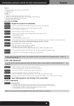
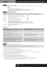
Functions:
Deceleration during opening (1 sec) and closing (4 sec).
Selectable automatic reclosing with pause time adjustable between 8-90 sec.
Selectable pre-flashing function during closing.
Electronic control of thrust force.
•
•
•
•
Operator assembly:
Join the steel profiles to the coupling, ensuring that the coupling is about halfway.
•
Photo 02
Photo 03
Photo 04
Equipment required for installation.
Fit the steel profile into place in the motor body untillstop is reached.
Wind the chain around the pinion.
•
•
Photo 06
Mount the chain transmission block, fitting the washer, spring, washer and nut.
Slightly tighten the chain.
•
•
Photo 07
Mount the bracket...
... using the screws, washers and nuts.
•
•
Photo 10
Mount the brackets, using the screws and washers.
Mark the position of the fixing bracket holes.
Drill the holes and fix the unit to the ceiling with the screw anchors provided in the accessory pack..
•
•
•
Photo 08
Fit the bracket in the centre of the door frame or to the wall using the screw anchors provided in the accessor y pack.
The minimum distance from the maximum sliding point of the door is 30 mm.
•
Photo 05
Mount the bracket using the screws and washers.
•
Photo 13
Release the plate of the limit switch block by undoing the screw
Pull the plate sideways freeing the ring nuts of the limit switches.
•
•
Photo 15
Act on the lower ring nut to adjust the closing limit switch point.
When the adjustment has been made, refit the ring nut locking plate tightening the screw.
•
•
Photo 14
Act on the upper ring nut to adjust the opening limit switch point.
•
Photo 09
Bend the brackets to size on the upper par t
•
Fit the draw bracket to the centre of the door using the screws provided in the accessor y pack.
•
Photo 11
Connect the arm to the draw bracket, taking care not to lock the arm.
•
Photo 12
To obtain better adjustment of the closing manoeuvre it might be necessar y to act on the drive rod of the door.
•
Photo 16
Limit switch adjustment:
Impor tant: The limit switch intervention does not lock the movement, but determines the star t of the deceleration phase of the
door
movement.
Caution: Arrange the power cable in such a way that it does not come into contact with the moving par ts (pinion – chain) as th
e
insulation could be damaged.
Trimmer adjustment
Drive Unit Equipment - See Drawing 17 for connections
Fig. 17
Photo 18
Pause time (RV1):
•
•
•
Completely turned anticlockwise, automatic closing is disabled (step-by-step operating mode).
Increasing the time, automatic closing is enabled from 8 sec. up to a maximum of about 90 sec.
It is recommended to disable automatic closing during the installation tests.
The factor y setting is zero. All turned anticlockwise.
When the card is powered, the courtesy light will flash to indicate that automatic closing is active.
Connector to plug in radio control, only for AS02190.
Semaphore card.
Buf fer batter y.
•
•
•
Options:
Содержание GECO LUX GECO60
Страница 23: ...Dis 17 F1 630mA ...
Страница 24: ...Foto 01 10 13 Ø4 Ø8 Foto 02 Foto 03 Foto 04 Foto 05 Foto 06 Foto 07 ...
Страница 25: ...Foto 08 Foto 09 Foto 10 Foto 11 Foto 12 Foto 13 Foto 14 Foto 15 ...
Страница 26: ...Foto 16 Foto 18 Foto 19 Foto 20 Foto 21 Foto 22 Foto 23 OUT 1 OUT 2 LED ROSSO START LEARN ...


