English
10
PROFESSIONAL AUTOMATIC SYSTEM FOR GATES AND GARAGE DOORS
Photo 19
Functions:
•
•
•
During the opening phase, it locks the movement.
During the closing phase it locks the movement and inver ts for 1 second to free the obstacle.
N.B. The more balanced the door the better the intervention of the control.
The factor y setting is at 50%, half-stroke.
Photo 20
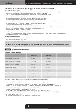
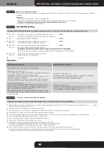
DIP SWITCH Setting
Motor torque adjustment (RV2)
Turning the trimmer anticlockwise, the inter vention threshold of the torque delivered by the motor is decreased, clockwise
increased.
Warning: DIP SWITCH modification is obtained by cutting the power for 10 sec. (card OFF) and then restoring it (card ON).
1
Pos. OFF -
Pos. ON -
During the closing phase the photocell stops the motion
During the closing phase the photocell inver ts the motion (*)
DIP 1
3
Pos. OFF -
Pos. ON -
Pre-flashing during the closing phase inactive (*)
Pre-flashing during the closing phase active
DIP 3
4
Pos. OFF -
Pos. ON -
Star t from photocell inter vention deactivated (*)
Star t from photocell inter vention activated
(AUTOMATIC CLOSING AND PRE-FLASHING DURING CLOSING MUST BE ENABLED).
The function allows controlling reclosing when the photocell is engaged and then released.
DIP 4
2
Pos. -
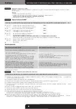
Type of operation (SEE OPERATION)
DIP 2
Operation
(*) Factor y setting
With automatic closing on
Without automatic closing on
For automatic closing see Pause time adjustment.
With DIP2 in OFF position (*):
At the START pulse the operator OPENS; during the opening phase
a subsequent START command stops the motion.
AUTOMATIC CLOSING is enabled at whatever point the door is, but
any START command is ignored.
When the pause time has elapsed, the operator CLOSES; during
this phase a START command locks or inverts the motion (see DIP1).
With DIP2 in OFF position (*):
At the START pulse the operator OPENS; during the opening phase
a subsequent START command stops the motion.
A fur ther START command CLOSES the door.
With DIP 2 in ON position:
At the START pulse the operator OPENS the door up to the limit
switch; during the opening phase a subsequent START command
is ignored. At the end of opening, AUTOMATIC CLOSING is ena-
bled, but any START command is ignored.
When the pause time has elapsed, the operator CLOSES; during
this phase a START command locks or inverts the motion (see DIP1).
With DIP2 in ON position:
At the START pulse the operator OPENS the door up to the limit
switch; during the opening phase the START command is ignored.
A fur ther START command CLOSES the door.
Fit the cover before powering the operator.
•
Photo 21
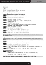
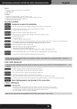
BEFORE ANY OPERATION ON THE SYSTEM, ENSURE THAT THE POWER SUPPLY IS DISCONNECTED.
Make all the connections to the buttons and connect the photocells and take DIP 5 in OFF. If several pairs of photocells are in
stalled,
the contacts must be placed in series.
If present, connect to flashlight to the respective output.
For the moment, cut out automatic reclosing, turning the trimmer RV1 completely anticlockwise.
Connect the unit to the mains (230 VAC) with the power cable provided.
Power the system. At this point, the power LED should come on. If this does not occur, check the connections to the 230 VAC lin
e.
Turn the thrust force adjusting trimmer - RV2 - by about 50%.
Press the START button; the door star ts the opening manoeuvre.
Press the STOP button to check proper functioning.
Repeat the opening manoeuvre until reaching the opening limit switch.
Check that the operator decelerates for 1 sec. in proximity of the opening position.
If it does not decelerate, check balancing of the door in opening position.
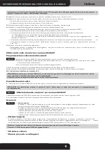
Press the START button; the door star ts the closing manoeuvre until reaching the closing limit switch.
As with the opening manoeuvre, check that the operator decelerates for 4 sec. in proximity of the closing position.
If it does not decelerate, check balancing of the door in closing position.
1
2
3
4
5
6
7
8
9
10
5
Pos. OFF -
Pos. ON -
Entrance “photo” activated (clamps M6 - M5)
Entrance “photo” not activated (*)
6
Not used
Содержание GECO LUX GECO60
Страница 23: ...Dis 17 F1 630mA ...
Страница 24: ...Foto 01 10 13 Ø4 Ø8 Foto 02 Foto 03 Foto 04 Foto 05 Foto 06 Foto 07 ...
Страница 25: ...Foto 08 Foto 09 Foto 10 Foto 11 Foto 12 Foto 13 Foto 14 Foto 15 ...
Страница 26: ...Foto 16 Foto 18 Foto 19 Foto 20 Foto 21 Foto 22 Foto 23 OUT 1 OUT 2 LED ROSSO START LEARN ...


