background image


43 

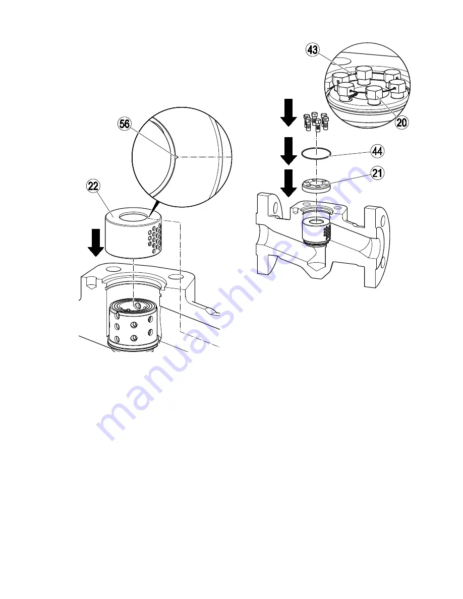
Mounting internals of equipment size DN 50 


Put the protective sleeve against wear (22) onto 
the sleeve insert and make sure that the 
marking notch (56) is centrally aligned and 
points towards the outlet. 


Put the thrust ring (21) into the body. 


Insert the retaining ring (44) into the body. 


Apply lubricant to the hexagon-head cap screws 
(20). 


Screw the hexagon-head cap screws into the 
thrust ring. 


Tighten the hexagon-head cap screws with a 
torque of 40 Nm. 


Secure the hexagon-head cap screws with the 
locking wire (43). 


Содержание ZK 29

Страница 1: ...Control Valve ZK 29 Original Installation Instructions 810685 05 ...

Страница 2: ... equipment 17 Transporting the equipment 17 Mounting and connecting the equipment 18 Preparing installation 18 Connecting the equipment 19 Checking the function 20 Starting up the equipment 20 Operating the equipment 23 After operation 23 Maintaining the equipment 25 Rinse the equipment 26 Disassembling the equipment 28 Assembling the equipment 37 Servicing the equipment and installing spare parts...

Страница 3: ...tallation operating manual together with the plant documentation for future reference Make sure that this installation operating manual is available to the operator The installation operating manual is part of the equipment Please hand over this installation operating manual when selling the equipment or passing it on Keep the applicable documents specified on page 7 together with this installatio...

Страница 4: ...plosion hazard Explosion risk if equipment is used that is not suitable for the environmental conditions When using the equipment in explosion risk areas make sure that The permissible surface temperature of the equipment for the place of installation must not be exceeded If electrically insulated equipment is installed appropriate measures must be taken to discharge any static electricity between...

Страница 5: ... and hot or pressurized fluid may escape Make sure that the equipment is only operated within the admissible service range and limits For more information on limits and pressure temperature ratings see name plate and the section Technical Data The equipment may be damaged if the connection of the equipment with the pipe is not stable enough or the equipment is not sufficiently supported Hot or pre...

Страница 6: ...d regulations for preventing fire and explosions as well as industrial safety regulations working on pressure equipment making pipe connections working with dangerous hot or pressurized fluids lifting and transporting loads observing all notes and instructions in this installation operating manual and the applicable documents connecting the power supply of the actuator Protective gear The required...

Страница 7: ...pment is fitted with a pneumatic diaphragm actuator you can detach the bonnet from the cover Different equipment variants are available The type designation has a code that indicates the respective variant The equipment is available in sizes between DN 25 and DN 150 The body is available as straight through or angle type The code letter D in the type designation indicates straight through and E in...

Страница 8: ...aphragm actuator In most cases the equipment described in this IOM is of the straight through type and has a spindle bearing for an electric rotary actuator If any other variant is shown or described it will be explicitly stated End connections The equipment is available with the following end connections Butt weld ends Socket weld ends Flanges The end connection is not specified in the type desig...

Страница 9: ...ion 1 Mechanical connection for actuator in equipment with rotary actuator this is a spindle bearing shown here 2 Pneumatic diaphragm actuator 3 Bonnet No Designation 4 Cover 5 Name plate 6 Flow direction arrow on both sides 7 Body ...

Страница 10: ...10 The yoke is fitted with the following items No Designation 8 Spindle 9 Scale marking indicator 10 Scale ...

Страница 11: ... different in equipment with rotary actuator and equipment with pneumatic diaphragm actuator Stuffing box in equipment with rotary actuator No Designation 11 Stuffing box gland 12 Packing rings 13 Distance sleeve No Designation 14 Base bushing 15 Hinged bolts ...

Страница 12: ...12 Stuffing box in equipment with pneumatic diaphragm actuator No Designation 12 Packing rings 14 Base bushing 16 Union nut No Designation 17 Packing gland 18 Grooved ring ...

Страница 13: ...equipment No Designation 19 Body gasket 20 Hexagon head screws with lock wire 21 Thrust ring 22 Anti wear element sleeve or ring depending on equipment type No Designation 23 Gasket 24 Stem 25 Seat ring 26 Sleeve insert pinned together with rivet ...

Страница 14: ...ecting for sealing fluid Sampling valve Mechanical lift stop not for equipment with pneumatic diaphragm actuator The stem lift in equipment fitted with a pneumatic diaphragm actuator can be limited by means of a handwheel attached to the actuator No Designation 27 Grease nipple 28 Sampling valve 29 Connecting for sealing fluid 30 Mechanical lift stop ...

Страница 15: ...lowing information The sign X in the Ex label signifies that operation at an excessive surface temperature caused by the medium must be avoided The equipment itself does not generate additional surface temperatures Once installed static electricity may arise between the equipment and the connected system During use in potentially explosive atmospheres the discharge or prevention of possible electr...

Страница 16: ...ontrols the fluid flow by successively opening a series of flash chambers When the stem is in the closed position the fluid flow is completely stopped and bubble tight closure is ensured When the equipment is closed the stem 24 is in the lowest position In this position the fluid flow is stopped During opening the stem is lifted off the seat ring 25 As a result the nozzle orifices 31 in the sleeve...

Страница 17: ... the equipment DANGER Risk of bruises if the equipment or component parts fall down Always wear protective gear when working on the equipment Use suitable lifting gear when moving or lifting the equipment and or component parts Make sure that the equipment cannot topple over To lift the equipment use only the valve body or the bonnet Make sure that nobody is standing below the lifted equipment The...

Страница 18: ...be of sufficient strength for the equipment including the actuator For more information on the weight of the equipment see the attached documents For more information on the weight of the actuator see the documents provided by the actuator manufacturer Preparing installation Remove the transport packaging Check the equipment for transport damage If you detect any transport damage please contact th...

Страница 19: ...d for installation with the stem in vertical position and the actuator mounted on top Other installation positions are possible Contact the manufacturer if you want to mount the equipment in a different position of installation Mount the equipment in the desired installation position Make sure that the equipment is supported by the pipes If the supports can only be attached directly to the equipme...

Страница 20: ...y out a performance test to check the functions of the equipment The stem must perform at least one full valve stroke Change if necessary the actuator settings as indicated in the operating manual of the actuator Starting up the equipment To finish the installation work please perform the following jobs Adjust the stuffing box Rinse the equipment Adjust the mechanical lift stop if provided Flush t...

Страница 21: ... box packing Tighten the screwed union until the following requirements are met The stuffing box must not leak The movement of the stem must not be impaired by the stuffing box If it is not possible to meet both requirements you have to replace the stuffing box packing Tighten the nuts on the two hinged bolts evenly Allow medium to flow through the equipment Move the spindle fully several times Ti...

Страница 22: ...ally flows through the equipment The optional stroke limiter is only available for equipment with a rotary actuator For equipment with a pneumatic diaphragm actuator you can adjust the stem stroke via a handwheel on the actuator LIft the stem until the desired minimum stem lift is reached Loosen the spring pin 32 Turn the adjustment nut 33 downwards until it hits the stop Re insert the spring pin ...

Страница 23: ...e to any moving equipment parts Make sure that the equipment cannot be switched on inadvertently The stem of the equipment is moved according to the actuator setting If you want to change the settings please follow the instructions given in the operating manual for the actuator In equipment with a mechanical stroke limiter you can determine the minimum stroke To do so proceed as described in the s...

Страница 24: ...ar For more information on suitable protective clothing and safety gear refer to the safety data sheet of the fluid in question DANGER Risk of bruises when working on the equipment during operation Switch off the equipment if you have to work close to any moving equipment parts Make sure that the equipment cannot be switched on inadvertently Attention Damage to the equipment due to improper mainte...

Страница 25: ...em is in closed position by measuring the temperature Replace leaky or worn components Spindle bearing Grease with the recommended grease see next section and a lint free cloth Lubricating nipples on spindle bearing equipment with rotating motor Apply the recommended grease see next section 12 months Secure actuator fastening Check that screws and bolts are secure Tighten loose screws to the speci...

Страница 26: ...cturer Replacing component parts To replace a component part proceed as follows Disassemble the equipment as described from page 28onwards Replace the component part with an original spare part from the manufacturer For details on how to order spare parts refer to the parts list The gaskets of the equipment must be replaced in any case Re assemble the equipment as described from page 37 onwards Ri...

Страница 27: ...ective clothing that is suitable for the fluid and if necessary wear protective gear For more information on suitable protective clothing and safety gear refer to the safety data sheet of the fluid in question Attention Equipment may be damaged by unsuitable cleaning fluid Rinse the pipe with the same fluid that is used during normal operation Make sure that the cleaning fluid does not damage the ...

Страница 28: ...itional tool is required Hexagon socket spanner US Allen wrench A F 19 mm The size of the tools depends on the equipment type Use only tools of suitable size Preparing the equipment for disassembly DANGER Personnel working on pipes are exposed to safety risks and may suffer severe injuries poisoning or even loss of life Make sure that no hot or hazardous fluid is in the equipment or the pipes Make...

Страница 29: ...tached documents For more information on the weight of the actuator see the documents provided by the actuator manufacturer Connect the lifting gear to the equipment or part that you want to lift For this purpose use a noose strap of sufficiently sturdy material Attach the noose strap to the lifting points or a flange The space required for disassembling and re assembling the equipment depends on ...

Страница 30: ... equipment with rotary actuator and equipment with pneumatic diaphragm actuator Removing the rotary actuator Undo the nuts 37 on the stud bolts 34 Remove the locking washers 36 from the stud bolts Lift off the actuator from the actuator flange 35 Remove the stud bolts 34 Equipment that cannot be retrofitted with an electric actuator is provided with a handwheel which is firmly attached to the thre...

Страница 31: ...ed during removal work Use suitable lifting gear to lift the components off the body Make sure that the components are not canted or tilted Make sure that the component parts are not damaged by physical shocks The required bearing capacity of the lifting gear depends on the equipment type Contact the manufacturer for more information on the weights of the individual parts Lift the cap 3 off the bo...

Страница 32: ...t of the body Take the protective sleeve against wear 22 out of the body Take the pinned sleeve insert 26 out of the body Take the seat ring 25 out of the body Take the gasket 23 out of the body Equipment of size DN 50 Remove the locking wire 43 from the hexagon head cap screws 20 Loosen the hexagon head cap screws 1 Push the thrust ring 21 downwards and hold it down 2 ...

Страница 33: ...y Take the pinned sleeve insert 26 out of the body Take the seat ring 25 out of the body Take the gasket 23 out of the body Equipment of size DN 80 Remove the locking wire 43 from the hexagon head bolts 20 Loosen the hexagon head bolts Take the smaller parts 45 out of the split ring Take the larger section 46 of the split ring out of the body Take the thrust ring 21 out of the body ...

Страница 34: ...ng 25 out of the body Take the sealing ring 23 out of the body Equipment of size DN 100 150 Remove the locking wire 43 from the hexagon head bolts 20 Loosen the hexagon head bolts Take the smaller parts 45 out of the split ring Take the larger section 46 of the split ring out of the body Take the thrust ring 21 out of the body ...

Страница 35: ... stuffing box packing There are different procedures for equipment with rotary actuator and equipment with pneumatic diaphragm actuator Removing the stuffing box in equipment with rotary actuator Knock the dowel pin 47 out of the position indicator 9 Loosen the hexagon nuts 48 on the hinged bolts 15 Fold the hinged bolts to the side Remove the washers 49 Screw the spindle 8 out of the threaded bus...

Страница 36: ...hing 14 Force the rings out of the stuffing box packing Packing rings 12 Distance sleeve 13 Grooved ring if provided Check the stuffing box chamber and all dissembled parts for signs of damage Replace all worn or damaged parts Clean all dirty parts Removing the stuffing box in equipment with pneumatic diaphragm actuator The body cover must be detached in order to remove the gland seal Removal of t...

Страница 37: ...n order to replace damaged parts Use a punch to knock out the rivet Check all parts for signs of damage Replace all worn or damaged parts Dismantling the sleeve insert The sleeve insert is pinned together with a slotted straight pin You only have to disassemble the sleeve insert if you want to replace sleeves Use a punch to knock the slotted straight pin out of the sleeve insert Assembling the equ...

Страница 38: ...nufacturer Use a punch to knock the slotted straight pin into the sleeve insert Connecting the stem to the spindle Align the stem and spindle so that the holes are lined up Drive a new rivet pin into the hole Mounting the gland packing Attention Malfunctions may occur if the packing rings are damaged Before installation discard and replace any damaged packing rings Make sure that the packing rings...

Страница 39: ...rking indicator 9 so that the hole for the dowel pin 47 is located above the hole in the spindle 8 Drive the dowel pin 47 into the holes using a mandrel Fold up the hinged bolts 15 in the slots of the stuffing box gland 11 Place the shims 49 and hexagon nuts 48 on the hinged bolts The torque required for tightening the screwed union depends on the condition of the stuffing box packing Tighten the ...

Страница 40: ... in the cap 2 Attention Malfunctions may occur if the packing rings are fitted incorrectly Make sure that the packing rings of the stuffing box are inserted in the following order The number of pure graphite rings depends on the size of the equipment The exact number is indicated in the parts list For more detailed information please contact the manufacturer Put the following parts of the stuffing...

Страница 41: ...ar to mount the component parts Do not tilt or skew the component parts during installation During installation make sure that the component parts are not damaged by physical shocks The required bearing capacity of the lifting gear depends on the equipment type Contact the manufacturer for more information on the weights of the individual parts Clean the sealing surface for the sealing ring in the...

Страница 42: ...o the sleeve insert and make sure that the marking notch 56 is centrally aligned and points towards the outlet Apply lubricant to the socket head cap screw 42 Screw the socket head cap screw 42 into the body Tighten the socket head cap screw with a torque of 160 Nm Insert a new body gasket 19 ...

Страница 43: ...s centrally aligned and points towards the outlet Put the thrust ring 21 into the body Insert the retaining ring 44 into the body Apply lubricant to the hexagon head cap screws 20 Screw the hexagon head cap screws into the thrust ring Tighten the hexagon head cap screws with a torque of 40 Nm Secure the hexagon head cap screws with the locking wire 43 ...

Страница 44: ...the slot in the outermost sleeve Put the thrust ring 21 into the body Insert the large parts of the segmented ring 46 into the body To fix the large parts of the segmented ring insert the small parts 45 into the body Screw the hexagon head cap screws 20 into the thrust ring Tighten the hexagon head cap screws with a torque of 100 Nm Secure the hexagon head cap screws with the locking wire 43 ...

Страница 45: ...body Insert the large parts of the segmented ring 46 into the body To fix the large parts of the segmented ring insert the small parts 45 into the body Screw the hexagon head cap screws 20 into the thrust ring Tighten the hexagon head cap screws with a torque of 100 Nm Secure the hexagon head cap screws with the locking wire 43 ...

Страница 46: ... the sealing surfaces in the body and on the cap for damage Replace damaged parts of the equipment Insert a new gasket 19 Clean the sealing surfaces Coat the thread of the stud bolts 41 with high temperature paste Position the cap 3 and spindle 8 on the body Place the nuts 40 on the stud bolts Attention Malfunctions due to incorrect tightening torques Tighten the screws nuts and bolts listed in th...

Страница 47: ...onent parts Make sure that the equipment cannot topple over Make sure that nobody is standing below the lifted equipment Inspect the sealing surfaces in the body and on the cover for damage Replace damaged parts of the equipment Clean the sealing surfaces Coat the thread of the stud bolts 41 with high temperature paste Make sure that a new body gasket 19 is inserted in the body 1 Position the cove...

Страница 48: ...nt or component parts fall down Use suitable lifting gear when moving or lifting the equipment and or component parts Make sure that the equipment cannot topple over Make sure that nobody is standing below the lifted equipment Put the feather key 59 into the threaded bush 50 Screw the stud bolts 34 handtight into the actuator Put the actuator onto the actuator flange 35 Put the locking washers 36 ...

Страница 49: ...w the lifted equipment Place the actuator on the cover 4 Hand tighten the groove nut 39 Install the coupling 38 between the spindle 8 and the actuator spindle Attention The equipment may suffer damage or malfunctions if actuator parts are not correctly aligned Make sure that the spindle is connected flush with the actuator spindle Connecting the actuator Connect the actuator properly to its power ...

Страница 50: ...Remove the defective component part from the equipment Attention Equipment may leak if the gaskets are damaged Always insert new main gaskets when assembling the equipment Check all gaskets seals and packing rings before installing them Replace any damaged gasket seal or packing ring Mount the new component part Check all component parts before re installing them Replace defective component parts ...

Страница 51: ...m lift is affected by foreign matter The nozzles are dirty or clogged by foreign particles Rinse the installation If necessary disassemble the equipment and clean the component parts During operation loud noises are audible The nozzles are dirty or clogged by foreign particles The stuffing box is leaking The stuffing box has not been tightened enough Adjust the stuffing box packing Make sure that ...

Страница 52: ...mental damage may be caused by poisonous fluid residues Before disposing of the equipment make sure that it is clean and free of fluid residues For the disposal of all materials observe the pertinent legal regulations concerning waste disposal Remove all residues from the equipment For the disposal of all residues observe the pertinent legal regulations concerning waste disposal Removing the equip...

Страница 53: ...nts provided by the actuator manufacturer Switch the installation off and protect it against unauthorised or unintended re activation WARNING Risk of severe injuries or death if the actuator is not removed correctly Before working on the actuator cut off power supply to the actuator Follow all instructions and observe all notes given in the operating manual for the actuator Make sure that only qua...

Страница 54: ...182F12Cl 2 Body DN 80 3 100 4 150 6 1 7357 A217WC6 Bonnet 1 7357 A217WC6 Cover 1 7335 A182F12Cl 2 Threaded bolt 1 7709 A193B16 Nuts 1 7709 A194 7 Technical data Dimensions and weights For information on the exact dimensions of the equipment see the dimensional drawing supplied with the equipment For information on the exact weights of the equipment see the dimensional drawing supplied with the equ...

Страница 55: ...and differential pressure Flowrates cold water A Differential pressure B Flowrate The chart shows the max flowrates of cold water at the extreme regulation position with linear characteristic curves and maximum Kvs value ...

Страница 56: ...ion factor into account The ascertained flowrate is reduced by the correction factor B Flowrate The chart shows the max flowrates of hot water at the extreme regulation position with linear characteristic curves and maximum Kvs value If p2 p1 0 5 multiply the flowrate read out by the correction factor K taken from the backpressure chart ...

Страница 57: ...ou can find precise information on the pressure and temperature ratings of your equipment on the name plate and in the data sheet Manufacturer s Declaration You can find details on the conformity assessment in accordance with European Directives in our Declaration of Conformity or our Declaration of Incorporation To request the valid Declaration of Conformity or Declaration of Incorporation please...

Страница 58: ...58 ...

Страница 59: ...59 ...

Страница 60: ...rld www gestra de GESTRA AG Münchener Straße 77 28215 Bremen Germany Telefon 49 421 3503 0 Telefax 49 421 3503 393 E Mail info de gestra com Web www gestra de 810685 05 07 2017 kx_mm 808539 05 GESTRA AG Bremen Printed in Germany ...

Отзывы: