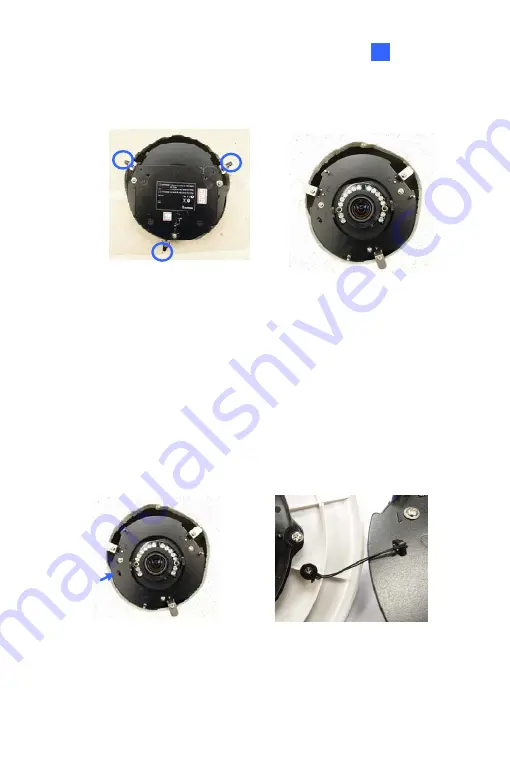
background image

Fixed IP Dome


18

9. 

On the back side, make sure the black plastic clips are slightly above 
the ceiling board and pointing outward. 


Back Side 

Front Side


10.  Tighten the bracket screws from the front side of the camera. 

11.  Connect the network and power cables to the camera. See 

18.4 

Connecting the Camera 

in the 

Quick Start Guide

12.  Access the live view. See 

24.2 Accessing the Live View

 in the 

Quick 

Start Guide

13.  Follow steps 6 and 7 in the 

Hard-Ceiling Mount

 section to adjust the 

angle, focus and zoom of the camera. 

14.  Use the housing cover thread and the thread lock screw to attach the 

housing cover to the camera body.   


197

Содержание GV-UNP2500

Страница 1: ...Before attempting to connect or operate this product please read these instructions carefully and save this manual for future use IC QG AP EN Quick Start Guide GV IP Camera...

Страница 2: ...assumed for incidental or consequential damages arising from the use of the information or products contained herein Features and specifications are subject to change without notice Note that memory c...

Страница 3: ...Note for Silica Gel Bags 1 Box Camera 1 1 1 Packing List 1 1 2 Overview 2 GV BX1200 Series 1500 Series 2400 Series 2500 Series 2600 3400 Series 5300 Series 12201 2 1 3 Accessory Installation 5 1 3 1 C...

Страница 4: ...2401 Series 2501 Series 3401 Series 5301 Series 34 GV MDR 36 5 3 Installation 39 GV MFD Series 39 GV MDR Series 41 5 4 Connecting the Camera 45 5 4 1 Wire Definition 45 5 4 2 Power and Network Connec...

Страница 5: ...1 Packing List 76 9 2 Overview 77 9 3 Installation 79 9 4 Connecting the Camera 86 10 Bullet Camera Part III 88 10 1 Packing List 88 10 2 Overview 89 10 3 Installation 90 10 3 1 Adjusting the Angles...

Страница 6: ...13 4 1 Wire Definition 127 13 4 2 Power Connection 127 14 Vandal Proof IP Dome Part I 128 14 1 Packing List 128 14 2 Overview 130 14 3 Installation 132 14 3 1 Hard Ceiling Mount 133 14 3 2 In Ceiling...

Страница 7: ...186 18 Fixed IP Dome 187 18 1 Packing List 187 18 1 1 Packing List for Hard Ceiling Mount 187 18 1 2 Packing List for In Ceiling Mount 188 18 2 Overview 189 18 3 Installation 191 18 3 1 Hard Ceiling...

Страница 8: ...Connecting the Camera 228 23 Pinhole Camera 229 23 1 Packing List 229 23 2 Overview 231 23 3 Installation 233 23 4 Connecting the Camera 237 24 Accessing the Camera 238 24 1 System Requirement 238 24...

Страница 9: ...Fixed Dome 260 Mini Fixed Rugged Dome 261 IR Arctic Box Camera 261 Target Mini Fixed Target Mini Fixed Rugged Dome 262 Bullet Camera 263 Ultra Bullet Camera 264 Target Bullet Camera 264 Vandal Proof...

Страница 10: ...H 264 H 265 series Camera Model No Lens Description GV BX1500 1F GV BX2500 1F 1 3 MP Low Lux 1 3 MP 1 3 MP Super Low Lux 2 MP WDR Pro 2 MP Super Low Lux GV BX1500 2F GV BX2500 2F Fixed 1 3 MP Low Lux...

Страница 11: ...3400 5V 3 MP WDR Pro GV BX5300 6V Varifocal 5 MP Box Camera GV BX1500 8F GV BX2500 8F GV BX3400 8F GV BX5300 8F Fixed 1 3 MP Super Low Lux 2 MP Super Low Lux 3 MP WDR Pro 5 MP GV BX1500 3V GV BX2500 3...

Страница 12: ...1100 2F 1 3 MP Low Lux GV EBX2100 0F 2 MP Low Lux Target Box Camera GV EBX2100 2F Fixed 2 MP Low Lux GV UBX1301 0F GV UBX1301 1F GV UBX1301 2F 1 3 MP GV UBX2301 0F GV UBX2301 1F GV UBX2301 2F 2 MP Ult...

Страница 13: ...el No Lens Description GV BX1500 E 1 3 MP Super Low Lux GV BX2400 E GV BX3400 E 2 MP 3 MP WDR Pro GV BX5300 E 5 MP GV BX2510 E 2 MP Super Low Lux P Iris IR Arctic Box Camera GV BX5310 E Varifocal 5 MP...

Страница 14: ...ed Rugged Dome GV MDR1500 2F GV MDR3400 2F GV MDR5300 2F Fixed 1 3 MP Super Low Lux 3 MP WDR Pro 5 MP GV MFD1501 0F GV MFD2401 0F GV MFD2501 0F GV MFD3401 0F GV MFD5301 0F 1 3 MP Super Low Lux 2 MP WD...

Страница 15: ...Low Lux 2 MP WDR Pro 2 MP Super Low Lux 3 MP WDR Pro 5 MP GV MFD1501 4F GV MFD2401 4F 1 3 MP Super Low Lux 2 MP WDR Pro GV MFD1501 5F GV MFD2401 5F GV MFD2501 5F GV MFD3401 5F GV MFD5301 5F 1 3 MP Su...

Страница 16: ...5 Super Low Lux WDR Pro GV BL5700 Varifocal 5 MP H 265 Low Lux WDR GV BL1210 GV BL2410 GV BL3410 Motorized Varifocal 1 3 MP Low Lux 2 MP WDR Pro 3 MP WDR Pro 3X Optical Zoom GV BL5310 Motorized Varifo...

Страница 17: ...GV BL2511 E 2 MP Super Low Lux 3X Optical Zoom P Iris IR Arctic Bullet Camera GV BL5311 E Varifocal Motorized 5 MP 2X Optical Zoom P Iris xv...

Страница 18: ...2 MP Super Low Lux P Iris GV UBL1211 GV UBL1511 GV UBL2411 GV UBL2511 GV UBL3411 Motorized Varifocal 1 3 MP Low Lux 1 3 MP Super Low Lux 2 MP WDR Pro 2 MP Super Low Lux 3 MP WDR Pro Auto Iris 3X Opti...

Страница 19: ...F GV UBL3401 2F GV UBL3401 3F Fixed 3 MP WDR Pro GV FD1200 GV FD2400 1 3 MP Low Lux 2 MP WDR Pro GV FD1500 GV FD2500 GV FD3400 Varifocal 1 3 MP Super Low Lux 2 MP Super Low Lux 3 MP WDR Pro Fixed IP D...

Страница 20: ...1510 GV FD2510 GV FD3410 Motorized Varifocal 1 3 MP Super Low Lux 2 MP Super Low Lux 3 MP WDR Pro 3x Optical Zoom P Iris GV EFD2101 2MP Super Low Lux WDR P iris GV EFD3101 3MP Super Low Lux WDR Pro P...

Страница 21: ...ver GV VD222D IK7 Transparent Cover GV VD223D IK7 Smoked Cover 2 MP GV VD320D IK10 Transparent Cover GV VD321D IK10 Smoked Cover GV VD322D IK7 Transparent Cover GV VD323D IK7 Smoked Cover 3 MP Vandal...

Страница 22: ...Optical Zoom GV VD5340 High Power IR LEDs Motorized Varifocal 5 MP 3X Optical Zoom GV VD2540 E 2 MP Super Low Lux 3X Optical Zoom Vandal Proof IP Dome GV VD5340 E High Power IR LEDs Motorized Varifoc...

Страница 23: ...pter The GV PA481 PoE adapter is designed to provide power and network connection to GV BX1200 E 2400 E 3400 E 5300 E over a single Ethernet cable GV PA482 PoE Adapter The GV PA482 PoE adapter is desi...

Страница 24: ...and each can be set as normally open NO or normally closed NC independently as per your requirement GV Relay V2 does not support GV EVD2100 3100 5100 Smoked Cover The smoked cover is an IK7 tinted ca...

Страница 25: ...re recorded to the memory card inserted to the GV IP Camera H 264 except GV IR Arctic Camera and Target Series which are not equipped with a memory card slot 2 Once the camera is connected to GV Syste...

Страница 26: ...the camera is under physical shock power interruption memory card detachment or when the memory card reaches the end of its lifespan No guarantee is provided for such causes The stored data can be lo...

Страница 27: ...amera please do not over tighten the Focus and Zoom screws The screws only need to be as tight as your finger can do it don t bother using any tools to get them tighter Doing so can damage the structu...

Страница 28: ...ullet Camera Vandal Proof IP Dome Mini Fixed Rugged Dome or Target Mini Fixed Rugged Dome outdoor be sure that 1 The camera is set up above the junction box to prevent water from entering the camera a...

Страница 29: ...ter opening the camera cover ensure the screws are tightened and the cover is in place 4 Make sure the housing cover is properly secured to prevent water from entering and damaging the inner housing x...

Страница 30: ...Note for Closing the Bullet Camera Cover To ensure that the camera performs its full capacity against water and dust tightly close and lock the camera cover as indicated below xxviii...

Страница 31: ...rproof Failures To avoid waterproofing failures do not open the screw on the camera body y The screw on Ultra Bullet Camera y The screw on Target Bullet Camera y The screw on GV EBL2101 y The screw on...

Страница 32: ...B hard drive 5 To connect a GV WiFi Adapter make sure it is connected before the camera is powered on Note for Silica Gel Bags 1 The silica gel bag loses it effectiveness when the dry camera is opened...

Страница 33: ...List Box Camera Terminal Block Fixed Focal or Varifocal Megapixel Lens Six Lens Rings Video Out Wire Camera Holder Power Adapter GV IPCAM Software DVD GV NVR Software DVD Warranty Card Note The power...

Страница 34: ...ew GV BX1200 Series 1500 Series 2400 Series 2500 Series 2600 3400 Series 5300 Series 12201 1 2 4 5 6 7 8 9 10 3 11 GV BX1200 Series 1500 Series 2400 Series 2500 Series 2600 3400 Series 5300 Series GV...

Страница 35: ...GV BX12201 No Name Description 1 Video Out Connects to a portable monitor for setting the focus and angle of Box Camera during initial installation 2 Memory Card Slot Receives a micro SD card SD SDHC...

Страница 36: ...Start Guide 12 Iris Screw Adjusts the iris of the camera 13 Zoom Screw Adjusts the zoom of the camera 14 Microphone Records the sounds 15 Focus Screw Adjusts the focus of the camera 16 Status LED Tur...

Страница 37: ...ter lens ring to the camera and then attach the lens onto the camera body Box Camera Three types of lens rings are provided for Box Camera 0 188 mm transparent color x 2 0 254 mm black color with a ma...

Страница 38: ...e Manual on the Software DVD 2 Access the Web interface of the camera 3 Select Video and Motion select Video Settings select Streaming 1 and set the IR Check Function setting to Trigger by Input 4 Cli...

Страница 39: ...Series 2400 Series 2500 Series 2600 3400 Series 5300 Series 12201 1 If you are using an auto iris model plug the iris control cable to the Auto Iris Connector on the camera 2 Connect to network using...

Страница 40: ...infrared illuminator For details see Infrared Illuminator and I O Terminal Block Box Camera Chapter GV IPCAM Firmware Manual on the Software DVD 6 Connect power using one of the following methods Plu...

Страница 41: ...2 Ultra Box Camera 2 1 Packing List Ultra Box Camera Supporting rack Screw x 3 Screw anchor x 3 Power Adapter GV IPCAM Software DVD GV NVR Software DVD Warranty Card Note The power adapter can be excl...

Страница 42: ...de 3 LAN PoE Connects to a 10 100 Ethernet or PoE 4 Microphone Records sounds 5 Memory Card Slot Receives a micro SD card SD SDHC version 2 0 only Class 10 to store recording data 6 DC 5V Terminal Blo...

Страница 43: ...ct and adjust your Ultra Box Camera 1 To install the device on the wall ceiling put the supporting rack on the desired location and make marks for screw anchors 2 Drill the marks and insert the screw...

Страница 44: ...s to the camera See 2 4 Connecting the Camera in the Quick Start Guide 6 Access the live view See 24 2 Accessing the Live View in the Quick Start Guide 7 Adjust the angle of the camera based on live v...

Страница 45: ...the power will be provided over the network cable The power and status LEDs shall turn on green 2 Use a standard network cable to connect the camera to your network 3 Optionally connect a speaker 4 In...

Страница 46: ...arget Box Camera 3 1 Packing List Target Box Camera Supporting Rack Screw x 3 Screw Anchor x 3 GV IPCAM Software DVD GV NVR Software DVD Warranty Card Note Power adapter can be purchased upon request...

Страница 47: ...ult Settings in the Quick Start Guide 2 LAN PoE Connects to a 10 100 Ethernet or PoE 3 Microphone Records sounds 4 DC 12V Terminal Block Connects to power LED Indicator Description Status LED The stat...

Страница 48: ...ust your Target Box Camera 1 To install the device on the wall ceiling put the supporting rack on the desired location and make marks for screw anchors 2 Drill the marks and insert the screw anchors 3...

Страница 49: ...ower cables to the camera See 3 4 Connecting the Camera in the Quick Start Guide 6 Access the live view See 24 2 Accessing the Live View in the Quick Start Guide 7 Adjust the angle of the camera based...

Страница 50: ...ardware Manual for Target Box Camera on the Software DVD Use the Power over Ethernet PoE function and the power will be provided over the network cable The power and status LEDs shall turn on green 2...

Страница 51: ...400 E 5300 E IR Arctic Box Camera Screw Anchor x 4 Screw x 4 Washer x 4 4 mm Torx Wrench 5 mm Torx Wrench Silica Gel Bag x 2 Adhesive Tape x 2 GV IPCAM Software DVD GV NVR Software DVD Warranty Card N...

Страница 52: ...ew Anchor x 4 Screw x 4 Washer x 4 5 mm Torx Wrench Silica Gel Bag Adhesive Tape Power Adapter DC 48V 2 5A 120 W max GV IPCAM Software DVD GV NVR Software DVD Warranty Card Note Optionally purchase a...

Страница 53: ...ription 1 Silica gel bag Desiccant that keeps the camera housing dry 2 IR power plug Supplies power to the built in IR LEDs 3 Focus Screw Adjusts the focus of the camera 4 Module screw Holds the modul...

Страница 54: ...Card Slot Inserts a micro SD card SD SDHC version 2 0 Class 10 to store recording data 3 Power LED Turns on when the camera is supplied with power 4 Status LED Turns on when the camera is ready for u...

Страница 55: ...he installation site and drill four holes for screw anchors 2 Insert the supplied screw anchors 3 Secure the camera to the wall using the supplied washers and screws 4 Connect the camera with wires an...

Страница 56: ...6 Based on the live view adjust the angle of the camera Loosen the indicated screw with the supplied big torx wrench and adjust the joint Tilt Adjustment Pan Adjustment 24...

Страница 57: ...adjust for image clarity based on the live view A Unscrew the cover with the supplied 4 mm torx wrench B Hold and unplug the connector IMPORTANT Unscrew and remove the cover carefully Pulling the cov...

Страница 58: ...k Start Guide Note Only GV BX5300 E contains an iris screw D Replace the silica gel bag Paste the sticker to the front side of the silica gel bag Press the sticker several times to make sure it adhere...

Страница 59: ...ver using the supplied torx wrench B Insert a memory card to the card slot Memory card slot C Replace the silica gel bag Paste the sticker to the silica gel bag Press the silica gel bag several times...

Страница 60: ...to connect t n external microphone eb Foll he steps bel he camera 1 Optionally connect a speaker green and a pink 2 Optionally connect a monitor using a Video Out wire Enable this function by selecti...

Страница 61: ...will be on 5 You are ready to access the live view Note For using the IR Arctic Box Camera ensure that you 1 enable the IR LED function on the Web interface after loading the default settings 2 disabl...

Страница 62: ...C TV Out 8 RJ 45 Ethernet PoE 1 Optionally connect the audio out green audio in pink digital output brown digital input yellow and GND 2 Optionally connect a monitor using a Video Out wire Enable this...

Страница 63: ...adapter is an optional accessory For detail see Options in the Quick Start Guide DC 48V Power Adaptor Power Hub Router Ethernet Cable Rear Panel PoE Use the supplied power adapter Connect the black w...

Страница 64: ...le stopper 2 pin terminal block Short Body RJ 45 Plug for GV MFD1501 series 2401 series 2501 series 3401 series 5301 series USB Audio Y cable for GV MFD1501 series 2401 series 2501 series 3401 series...

Страница 65: ...el bag x 2 Adhesive Tape x 2 Ferrite core for vehicle installation GV IPCAM Software DVD GV NVR Software DVD Warranty Card Note 1 The power adapter can be excluded upon request 2 When purchasing GV MD...

Страница 66: ...era to default settings See 27 Restoring to Default Settings 6 DC 5V Power Port Connects to power 7 LAN PoE Connects to a 10 100 Ethernet or PoE 8 Memory Card Slot Inserts a micro SD card SD SDHC vers...

Страница 67: ...1 2 3 4 LED Name Description 1 Link Turns on green when the network is connected 2 ACT Turns on orange when data are being transmitted 3 Status Turns on red when the system is ready 4 Power Turns on g...

Страница 68: ...isture from entering the camera 3 Lens Receives image inputs 4 Rotation Disc Rotates the camera lens 5 Pan Disc Pans the camera lens 6 Tilt Screw Loosens to tilt the camera 7 Built In Microphone Provi...

Страница 69: ...t twice when the system is ready 10 LAN LED Turns on when the network is connected 11 Memory Card Slot Receives a micro SD card SD SDHC version 2 0 only Class 10 to store recording data IMPORTANT In c...

Страница 70: ...5300 series Select an option based on your installation environment 1 Waterproof M12 4 Pin Female Connector The M12 connector is used for motor vehicles 14 7 mm 0 58 2 Small Waterproof Connector For t...

Страница 71: ...for screw anchors If you want to run the cables inside the ceiling make a round mark with a diameter of 2 5 cm 3 Drill the marks and insert the screw anchors 4 Secure the Mini Fixed Dome to the ceilin...

Страница 72: ...Memory Card Slot 9 Adjust image clarity using the GV IP Device Utility program For details see 24 3 Adjusting Image Clarity in the Quick Start Guide 10 Secure the housing cover using the supplied tor...

Страница 73: ...the camera faces 2 Drill one hole on each of the two curves for screw anchors Drill the circle 30 mm in diameter if you want to run the cable into the ceiling Drill a hole on each 30 mm 3 Insert the...

Страница 74: ...RJ 45 connector on one end only B Connect the Ethernet cable to the camera cable C Paste the sticker to the camera cable and slide in all the components as shown below D Move all the components towar...

Страница 75: ...Item 5 must be secured tightly to waterproof the cable 7 Access the live view See 24 2 Accessing the Live View in the Quick Start Guide 8 Adjust the angles based on the live view Pan Adjustment Tilt A...

Страница 76: ...e Clarity in the Quick Start Guide 10 Insert a memory card SD SDHC version 2 0 only Class 10 into the memory card slot 11 Replace the silica gel bag 12 Secure the housing cover using the supplied torx...

Страница 77: ...network Wired connection with PoE Use a Power over Ethernet PoE adapter to connect the camera to the network and the power will be provided at the same time Wired connection with network cable GV MFD...

Страница 78: ...tion To install the Mini Fixed Rugged Dome on a vehicle clip the ferrite core to the camera cable The ferrite core must be attached as close as possible to the camera with the maximum distance of 15 c...

Страница 79: ...rget Mini Fixed Dome 6 1 Packing List Target Mini Fixed Dome Screw x 2 Screw Anchor x 2 Focus Adjustment Clip or Ring GV IPCAM Software DVD GV NVR Software DVD Warranty Card Note The power adapter can...

Страница 80: ...rophone Receives sound 5 Default Button Resets the camera to default settings See 27 Restoring to Default Settings 6 DC 12V Port Connects to power 7 LAN PoE Connects to a 10 100 Ethernet or PoE a Stat...

Страница 81: ...e installing site is shielded from rain and moisture 1 Open the housing cover by turning 2 Place the camera where you want to install it and make 2 marks on the ceiling or the wall for screw anchors I...

Страница 82: ...l with the self tapping screws 6 Access the live view For details see 24 2 Accessing the Live View in the Quick Start Guide 7 Loosen the tile screw and pan screw adjust the angles based on the live vi...

Страница 83: ...e GV IPCAM Hardware Manual for Target Mini Fixed Dome on the Software DVD Use the Power over Ethernet PoE function and the power will be provided over the network cable The power and status LEDs shall...

Страница 84: ...nchor x 2 Focus Adjustment Ring Installation Sticker Conduit Converter RJ 45 Connector Waterproof Rubber Set for RJ45 and DC12V Torx Wrench Silica Gel Bag x 2 Adhesive Tape x 2 Concave Hexagon Wrench...

Страница 85: ...ll the supplied conduit converter with a PG21 conduit connector and a self prepared conduit pipe of 1 2 3 4 or 1 to the camera Do not use a 1 2 pipe if you use the power adapter for power supply becau...

Страница 86: ...t angle 4 Default Button Resets the camera to default settings See 27 Restoring to Default Settings 5 DC 12V Port Connects to power 6 LAN PoE Connects to a 10 100 Ethernet or PoE a Status Turns on gre...

Страница 87: ...roof rubber set to waterproof the cable 1 Paste the installation sticker where you want to install and drill two holes that are at a diagonal To run the cables inside the wall or ceiling drill a large...

Страница 88: ...he 2 supplied screws to secure the back plate onto the ceiling or the wall where the screw anchors were inserted 6 Prepare an Ethernet cable with the RJ 45 connector on one end only 7 Remove the water...

Страница 89: ...1 For network cable For network cable PoE For power cable A Slide the waterproof rubber set and the waterproof cap you previously removed through the cable s as shown below 2 1 B Connect the supplied...

Страница 90: ...able opening Use the supplied ruler to make sure the length of the cable s from the bottom of the opening to the end of the cable is under 10 cm E Cap the cable opening with the waterproof cap Use the...

Страница 91: ...cting the Camera 11 Secure the camera to the back plate by tightening the three screws as shown in Step 4 12 Access the live view For details see 24 2 Accessing the Live View 13 Adjust image clarity u...

Страница 92: ...15 Attach the silica gel bag to the place indicated below and secure the housing cover using the torx wrench 60...

Страница 93: ...IPCAM Hardware Manual for Target Mini Fixed Rugged Dome on the Software DVD Use the Power over Ethernet PoE function and the power will be provided over the network cable The power and status LEDs sh...

Страница 94: ...r x 3 Torx Wrench x 2 Sun Shield Cover Kit Sun Shield Cover Philips Head Screws x 2 Plastic Screw Spacer x 2 and Hexagon Screw x 2 Silica Gel Bag x 2 2 Pin Terminal Block Power Adapter GV IPCAM Softwa...

Страница 95: ...t Receives a micro SD card SD SDHC version 2 0 only Class 10 2 Zoom Screw Holds the zoom lens in place 3 Focus Screw Holds the focus lens in place 4 Default Button Resets the camera to default setting...

Страница 96: ...move the protection sticker from the camera s cover 4 Connect the power network and other cables to the camera See 8 4 Connecting the Camera in the Quick Start Guide 5 Access the live view See 24 2 Ac...

Страница 97: ...d SD SDHC version 2 0 only Class 10 into the memory card slot See 8 3 2 Adjusting Lens and Inserting a Memory Card in the Quick Start Guide 8 Fasten the camera s cover 9 Install the sun shield cover t...

Страница 98: ...offer easy and flexible ceiling wall mount installation First Shaft You can adjust the camera body by 360 degrees to the right or the left 1 Unscrew the panning lock screw with the torx wrench Torx W...

Страница 99: ...lock screw with the torx wrench Torx Wrench Tilting Lock Screw 2 Hold the camera body and move the camera base to the right to separate the camera gears Camera Body Camera Gears Move the Camera Base t...

Страница 100: ...aft You can adjust the camera base by 360 degrees 1 Unscrew the base fixing screw with the torx wrench Torx Wrench Base Fixing Screw 2 Adjust the angle of camera base and fasten the base fixing screw...

Страница 101: ...o adjust for image clarity follow the steps below For models with zoom and focus screws pull out the camera and remove the silica gel bag to access its focus and zoom screws Use GV IP Device Utility t...

Страница 102: ...elow A Loosen the fixing screw Fixing Screw B Slightly pull out the camera module C Insert a micro SD card SD SDHC version 2 0 only Class 10 into the memory card slot Memory Card Slot D Push the camer...

Страница 103: ...Bullet Camera Part I 8 4 Insert a new silica gel bag to the camera module Silica Gel Bag All Bullet Camera except GV BL2510 E 5310 E GV BL2510 E 5310 E 71...

Страница 104: ...ews either on top or below the camera Hexagon Screws 2 Put the sun shield cover on top of hexagon screws Make sure to aim the rear hexagon screw at the edge of the sun shield cover s aperture for opti...

Страница 105: ...of the Bullet Camera is illustrated and defined below Ethernet PoE Digital In Red DC 12V AC 24V Brown Digital Out Orange DC 12V AC 24V Black GND Yellow Audio In Red Audio Out Green No Wire Color Defin...

Страница 106: ...n Red DC 12V AC 24V Brown Digital Out Orange DC 12V AC 24V Black GND Yellow Audio In Brown Audio Out Green No Wire Color Definition 1 Red Digital In 2 Brown DC 12V AC 24V 3 Orange Digital Out 4 Black...

Страница 107: ...se a Power over Ethernet PoE adapter to connect the camera to the network and the power will be provided at the same time Plug the power adaptor to the terminal block as shown below 1 Insert the black...

Страница 108: ...nal Block Power Adapter Installation Sticker Ruler Stand Kit Conduit Converter PG21 Conduit Connector RJ 45 Connector M3 Screw x 2 Cable Tie Mounting Kit M4 Screw x 3 Nut x 3 Plate x 3 GV IPCAM Softwa...

Страница 109: ...cription 1 Memory Card Slot Receives a micro SD card SD SDHC version 2 0 only Class 10 2 Zoom Screw Holds the zoom lens in place 3 Focus Screw Holds the focus lens in place 4 Default Button Resets the...

Страница 110: ...me Description 1 LAN PoE Connects to a 10 100 Ethernet or PoE 2 Audio In Connects a microphone for audio input 3 Audio Out Connects a speaker for audio output 4 I O Terminal Block Connects to I O devi...

Страница 111: ...ra 1 Paste the supplied sticker to the ceiling wall For wall installations make sure the arrow on the sticker points toward the ceiling 2 Drill the shaded area and insert the screw anchor into the thr...

Страница 112: ...4 Loosen the indicated screws and remove the back plate Back Plate 5 Align and secure the black plate to the wall ceiling with the supplied self tapping screws 80...

Страница 113: ...rter using the supplied M3 screws IMPORTANT For GV BL2511 E 5311 E connected with a power adapter only install the conduit converter to the indicated exit 7 Install the Ethernet cable 1 Twist off and...

Страница 114: ...IMPORTANT Use the supplied ruler and leave about 10 cm of the Ethernet cable between the connector and the cable seal 3 Re install the cable seal Make sure it is installed tightly to waterproof the ca...

Страница 115: ...ough part 1 2 3 and 4 of the conduit connector Tip To make the threading easier it is advised to thread the wires in the order described here For part 2 there are 8 holes each labeled with its diamete...

Страница 116: ...conduit connector to make sure the wires are properly sealed 9 Install the base to the back plate on the wall 10 Connect the wires to the camera A Install the terminal blocks to the power adapter and...

Страница 117: ...the angles of the camera based on the live view Three shafts can be adjusted See 8 3 1 Adjusting the Angles 14 To adjust the focus and insert a micro SD card SD SDHC version 2 0 Class 10 see 8 3 2 Adj...

Страница 118: ...Ethernet PoE adapter to connect the camera to the network and the power will be provided at the same time Plug the power adaptor to the terminal block as shown below For all models except GV BL2511 E...

Страница 119: ...orts one digital input and one digital output of dry contact Pin Function 1 Digital Output 2 GND I O 1 2 3 3 Digital Input For details on how to enable an installed I O device see I O Settings Adminis...

Страница 120: ...crew for Supporting Rack x 3 Screw Anchor x 3 Silica Gel Bag x 2 Screw for Mounting Kit x 3 Nut for Mounting Kit x 3 Hex Wrench RJ 45 Connector x 2 GV IPCAM Software DVD GV Software DVD Warranty Card...

Страница 121: ...Description 1 Memory Card Slot Receives a micro SD card SD SDHC SDXC Class 10 2 Default Button Resets the camera to default settings For details see 27 Restoring to Default Settings later in the Quic...

Страница 122: ...elow 1 Unscrew the camera body remove the sun shield mount and loosen the camera cover from the camera Screws Sun Shield Mount Camera Cover 2 Insert a micro SD card SD SDHC SDXC Class 10 into the card...

Страница 123: ...amera cover fasten the sun shield mount and screw the camera body Sun Shield Mount 5 Slide the sun shield cover onto the top of the camera Adjust the position of the cover before fully securing the co...

Страница 124: ...conduit connector B Disintegrate the removed conduit connector Thread the Ethernet cable through the 3 parts C Assemble the conduit connector Note If you can t plug the self prepared RJ 45 connector i...

Страница 125: ...To avoid waterproofing failures the top of the camera must be facing upward for wall mount 8 Connect the wires and cable connector to the camera See 10 4 Connecting the Camera 9 Access the live view...

Страница 126: ...to be adjustable in two shafts for easy and flexible installation First Shaft You can adjust the camera base by 360 1 Unscrew the base fixing screw with the hex wrench 2 Adjust the angle of camera ba...

Страница 127: ...Shaft You can adjust the camera body to the desired angle by tilting the camera module 1 Unscrew the tilting lock screw with the hex wrench 2 Adjust the angle of camera body to the desired angle 3 Fas...

Страница 128: ...elow 1 Loosen the camera s cover 2 To adjust for image clarity by adjusting the focus and zoom screws For details see 2 2 Adjusting Image Clarity GV IPCAM Firmware Manual Zoom Screw Focus Screw IMPORT...

Страница 129: ...dio input and 1 audio output The wires are illustrated and defined below Ethernet PoE 4 Pin terminal block 5 Pin terminal block 1 2 3 4 5 6 7 8 9 No Wire Name Definition 1 DI Digital In 2 DI Digital i...

Страница 130: ...to supply power to the camera y Use a Power over Ethernet PoE adapter to connect the camera to the network and the power will be provided at the same time y Connect the wires of your power adapter to...

Страница 131: ...x 3 Plastic Screw Anchor x 3 Torx Wrench Sun Shield Cover Kit Sun Shield Cover Philips Head Screw x 2 Plastic Screw Spacer x 2 and Hexagon Screw x 2 Cable connector for waterproof LAN connector only...

Страница 132: ...n the Quick Start Guide 2 Default Button Resets the camera to default settings See 27 Restoring to Default Settings in the Quick Start Guide 3 LAN PoE Cable Connects to a 10 100 Ethernet or PoE 4 Memo...

Страница 133: ...ovides two connector types Select an option based on your installation environment Option 1 Waterproof To waterproof the cable install the supplied cable connector See 11 4 1 Waterproofing the Cable i...

Страница 134: ...sion 2 0 only Class 10 into the card slot and replace the silica gel bag C Secure the back cover with the supplied torx wrench 2 Install the sun shield cover to the camera A Fasten the hexagon screw s...

Страница 135: ...GeoVision logo on the sun shield cover should be closer to the front of the camera C Fasten the Philips head screws with the plastic screw spacers to mount the sun shield cover onto the camera y Ceili...

Страница 136: ...ount Secure the black rubber and the camera stand to the other screw hole on the top B Wall Mount Secure the black rubber and the camera stand to one of the screw holes on the bottom Wall Mount Ceilin...

Страница 137: ...r to the camera See 11 4 1 Waterproofing the Cable and 11 4 2 Connecting the Camera 7 Access the live view For details see 2 1 Accessing the Live View GV IPCAM Firmware Manual 8 Adjust angles of the c...

Страница 138: ...cable of the LAN connector using the supplied cable connector The cable connector can be dissembled into 5 parts LAN Connector Cable Connector 1 2 3 4 5 1 Cut off the RJ 45 connector on one end of the...

Страница 139: ...ve all the components toward the LAN connector fit item 4 to item 2 secure item 3 to the LAN connector Item A and finally secure item 5 to item 2 tightly IMPORTANT Item 5 must be secured tightly to wa...

Страница 140: ...The supplied 4 pin data cable provides connections for power ground 1 sensor input and 1 alarm output The wires are defined below No Wire Color Definition 1 Red DC 5V 2 Green Digital In 3 Blue Digital...

Страница 141: ...PoE adapter to connect the camera to the network and the power will be provided at the same time Plug the power adaptor to the terminal block as shown below 1 Insert the black wire of the data cable t...

Страница 142: ...amera Sun Shield Cover Silica Gel Tape x 2 Supporting Rack Screw for Supporting Rack x 3 Screw Anchor x 3 Screw for Sun shield Cover Washer Terminal Block GV IPCAM Software DVD GV NVR Software DVD War...

Страница 143: ...iew No Name Description 1 Power Connector Connects to the data cable For details see 12 4 1 Connecting the Camera 2 Default Button Resets the camera to default settings See 27 Restoring to Default Set...

Страница 144: ...opened If you open the camera to access the load default button replace the silica gel tape by taping the new silica gel tape to the inside of the camera cover Make sure you conceal the silica gel ta...

Страница 145: ...live view replace Silica Gel Tape prior to installation and use waterproof tape to seal the RJ 45 connector 1 Slide the sun shield cover onto the top of the camera Note The GeoVision logo on the sun s...

Страница 146: ...un shield cover 4 Wall Mount A Insert and tighten the supplied screw on the sun shield cover B Secure the supporting rack to the bottom IMPORTANT To avoid waterproofing failures do not open the screw...

Страница 147: ...Bullet Camera 115 12 5 Thread the Ethernet cable into the conduit connector For details see step 6 10 3 Installation Note The size of RJ 45 connector must be within 14 mm to plug into the jack of the...

Страница 148: ...ra on a plain surface 7 Remove the protection sticker from the camera s cover 8 Connect the wires and cable connector to the camera See 12 4 Connecting the Camera in the Quick Start Guide 9 Access the...

Страница 149: ...Connecting the Camera 12 4 1 Wire Definition The data cable provides connections for power ground and network access The wires are defined below No Wire Color Definition 1 Red DC 12V 2 Black Ground 3...

Страница 150: ...me time Plug the power adaptor to the terminal block as shown below The power adapter is an optional device For detail see Options in the GV IPCAM Hardware Manual for Target Bullet Camera on the Softw...

Страница 151: ...to GV EBL2101 13 1 Packing List Target Bullet Camera Sun Shield Cover Silica Gel Bag x2 Screw for Supporting Rack x 3 Screw Anchor x 3 Screw for Sun shield Cover x 2 Washer x 2 RJ45 Connector Terminal...

Страница 152: ...GV NVR Software DVD Warranty Card Note Power adapter can be purchased upon request 120...

Страница 153: ...No Name Description 1 Zoom Screw Holds the zoom lens in place 2 Focus Screw Holds the focus lens in place 3 Default Button Resets the camera to default settings See 27 Restoring to Factory Default Se...

Страница 154: ...ou can install the camera to the ceiling or wall Follow the steps below 1 Replace the Silica Gel Bag A Remove the camera cover from the camera B Loosen the camera s screws and the hexagon pillars as i...

Страница 155: ...camera from the camera body D Cut the 2 silica gel bags apart with scissors and place the new silica gel bags at the lower half of the camera body 2 Secure the 2 hexagon pillars to the upper and lower...

Страница 156: ...back of the camera Adjust the position of the cover before fully securing the cover with the washer and the screw Note 1 The GeoVision logo on the sun shield cover should be closer to the front of the...

Страница 157: ...hread the Ethernet cable into the conduit connector For details see step 6 10 3 Installation Note If you can t plug the self prepared RJ 45 connector into the jack of the conduit it is suggested to us...

Страница 158: ...id waterproofing failures the top of the camera must be facing upward for wall mount 7 Connect the wires and cable connector to the camera See 13 4 Connecting the Camera 8 Access the live view For det...

Страница 159: ...Wire Definition The data cable provides connections for power ground and network access The wires are defined below No Wire Color Definition 1 Red DC 12V 2 Black Ground 3 Black thick PoE Ethernet 13...

Страница 160: ...2D 123D 220D 221D 222D 223D 320D 321D 322D 323D 1500 2400 3400 14 1 Packing List Vandal Proof IP Dome Silica Gel Bag x 2 Screw Anchor x 4 Torx Wrench Ceiling Screw x 4 Blue Screw x 3 T Cap Screw x 3 S...

Страница 161: ...IP Dome Part I 14 GV IPCam Software DVD Power Adapter GV NVR Software DVD Warranty Card Note 1 Focus Adjustment Cap is only needed and supplied for IK10 models 2 The power adapter can be excluded upon...

Страница 162: ...3 Default Button Resets the camera to default settings See 27 Restoring to Default Settings in the Quick Start Guide 4 Memory Card Slot Receives a micro SD card SD SDHC version 2 0 only Class 10 to st...

Страница 163: ...Vandal Proof IP Dome Part I 14 No Name Description 9 Zoom Screw Adjusts the zoom of the camera 10 Focus Screw Adjusts the focus of the camera 11 Silica Gel Bag Absorbs moisture in the camera body 131...

Страница 164: ...ome hard ceiling mount and in ceiling mount Note You can also install the camera on a power box of the 4 square and double gang type using the standard package to ceilings wall corners concave or conv...

Страница 165: ...Vandal Proof IP Dome Part I 14 14 3 1 Hard Ceiling Mount 1 Unpack the camera package and take out the camera body Unscrew the housing cover Unscrew thread lock 133...

Страница 166: ...housing Take out the camera body 2 Mark the position of four screw holes on the desired installation location and drill holes in the marked locations Drill the ellipse part if you wish to put the wir...

Страница 167: ...conduit entry at the side of the back cover Alternatively pass the wires through the ellipse hole at the bottom of the back cover 7 Connect the network and power cables to the camera See 14 4 Connect...

Страница 168: ...Pan Adjustment Tilt Adjustment Rotational Adjustment 136...

Страница 169: ...GV IP Device Utility program For details see 22 3 Adjusting Image Clarity in the Quick Start Guide Focus Screw Zoom Screw 11 Screw on the thread lock as shown in step 1 12 Replace the silica gel bag a...

Страница 170: ...the Hard Ceiling Mount section to remove the housing cover thread lock and back cover and take out the camera body 2 Cut out a circle with a diameter of 142 mm on the ceiling 3 Insert a blue screw to...

Страница 171: ...blue screw until the plastic clip moves half way down Plastic Clip 5 Secure a T cap on top of the blue screw with a small screw cap and a T cap screw Do not tighten the small screw cap so that the pla...

Страница 172: ...t the network and power cables to the camera See 14 4 Connecting the Camera in the Quick Start Guide 10 Access the live view See 24 2 Accessing the Live View in the Quick Start Guide 11 Follow steps 9...

Страница 173: ...strated and defined below TV out Audio out green Audio in red Digital in oragne Ground yellow Digital out brown Shielding ground DC 12V AC 24V DC 12V AC 24V Ethernet PoE No Wire Color Definition 1 Bla...

Страница 174: ...onnect the black BNC connector to a monitor and select your signal format NTSC or PAL at the TV Out field on the Web interface For details see Video Settings Administrator Mode Chapter GV IPCam Firmwa...

Страница 175: ...apter to connect the camera to the network and the power will be provided at the same time Plug the power adaptor to the terminal block as shown below 1 Insert the thin black wire of the Vandal Proof...

Страница 176: ...s chapter applies to GV VD1530 1540 2430 2440 2530 2540 2540 E 3430 3440 5340 5340 E 15 1 Packing List Vandal Proof IP Dome Torx Wrench 3 Pin Terminal Block Audio wires Power Adapter TV out wire Focus...

Страница 177: ...5 Connector x 2 Back Plate Installation sticker 1 1 1 Ceiling mount template Screw Anchor x 4 Long Screw x 4 Flat Screw Short Screw x 2 Silica Gel Bag Sticker for Silica Gel Bag Ruler Conduit Converte...

Страница 178: ...uit pipe to the camera Power will have to be supplied through a PoE adapter because the power adapter wire does not fit in a 1 2 pipe You will have to purchase your own PG21 conduit connector if you w...

Страница 179: ...Vandal Proof IP Dome Part II 15 15 2 Overview 1 2 3 4 5 6 8 7 9 10 12 11 13 14 147...

Страница 180: ...6 Memory Card Slot Inserts a micro SD card SD SDHC version 2 0 only Class 10 to store recording data 7 Audio Out Connects to a speaker for audio output 8 DC 12V AC 24V Connects to power 9 I O Termina...

Страница 181: ...age to ceilings wall corners concave or convex and poles using optional mounting kits For details on these installations see GV Mount Accessories Installation Guide on the Software DVD IMPORTANT When...

Страница 182: ...r wires and I O wires optional through the conduit entry and then through part 1 2 3 and 4 of the conduit connector Tip 1 To make the threading easier it is advised to thread the wires in the order de...

Страница 183: ...ors and the cable seal leave at least 11 cm of audio TV out wires between their connectors and the cable seal 2 The plugs are used to prevent water from entering the camera housing Keep the unused hol...

Страница 184: ...Ethernet cable the end with no RJ 45 connector from the back panel through the cable seal IMPORTANT Use the supplied ruler and leave about 11 cm of the Ethernet cable between the connector and the ca...

Страница 185: ...es See 15 4 Connecting the Camera in the Quick Start Guide B Install the supplied RJ 45 connector to the Ethernet cable C Plug all the connectors to the camera panel Tip Unscrew the indicated screws a...

Страница 186: ...ve the wires come out from position A B or both The instructions here describe sorting wires for position A A B From the back of the camera housing unscrew and rotate the plate to one side sort out th...

Страница 187: ...ces 1 1 1 Ceiling mount template A B B Drill 3 holes for screws The recommended ones are indicated as 1 C Insert the screw anchors to the 3 holes D Depending on how you want to run the wires see step...

Страница 188: ...flat screw for number 1 and small screw for number 2 1 2 B Thread all the wires into the ceiling and connect them C Secure the camera using the torx wrench 8 Access the live view See 24 2 Accessing th...

Страница 189: ...Vandal Proof IP Dome Part II 15 Pan Adjustment Tilt Adjustment Rotational Adjustment 157...

Страница 190: ...e torx wrench IMPORTANT If the center of the camera view is less than 25 to the ceiling or lower than the grey line as illustrated below disassemble the indicated ring so the view is not obstructed Ho...

Страница 191: ...4 1 Connecting the Power Cable There are two ways to supply power to the camera Use a Power over Ethernet PoE adapter to connect the camera to the network and the power will be provided at the same t...

Страница 192: ...e digital input and one digital output of dry contact I O 1 2 3 Pin Function 1 Digital Output 2 GND 3 Digital Input For details on how to enable an installed I O device see I O Settings Administrator...

Страница 193: ...of IP Dome Part III The information in this chapter applies to GV VD3700 5700 16 1 Packing List H 265 Vandal Proof IP Dome Torx Wrench Long Screw x 4 Screw Anchor x 4 Back Plate Short Screw for Back P...

Страница 194: ...2 Sticker for Silica Gel Bag x 2 GV IPCAM Software DVD GV Software DVD Pan Angle Notification Card Warranty Card Note The supplied anti drop wire is used for attaching the camera body to GV Mount206 F...

Страница 195: ...Vandal Proof IP Dome Part III 16 16 2 Overview 1 2 4 5 3 163...

Страница 196: ...icro SD card SD SDHC SDXC Class 10 to store recording data UHS II card type is not supported 3 Base Screw Loosen to pan the camera 4 Tilt Screw Loosen to tilt the camera 5 Default Button Reset the cam...

Страница 197: ...can install the camera on the ceiling 1 Remove the housing cover with the supplied torx wrench 2 Thread the Ethernet cable into conduit connector For details see step 6 10 3 Installation Note If you...

Страница 198: ...ate to the ceiling A Paste the sticker to the ceiling The triangle on the sticker indicates the direction that the camera faces Ceiling mount template 1 1 1 1 B Drill 4 holes for screws The recommende...

Страница 199: ...te to the rear side of the camera with the supplied short screws 5 Insert your micro SD card into the SD card slot 6 Access the live view See 2 1 Accessing the Live View GV IPCAM Firmware Manual 7 Bas...

Страница 200: ...era is marked with a white line in front of the memory card slot When adjusting the camera pan angle avoid turning the camera for more than 180 degrees in either direction Continuous rotation greater...

Страница 201: ...art III 16 8 Paste the silica gel bag with a sticker right behind the lens 9 Secure the housing cover back to the camera body Note You can remove the cable stopper to thread the camera s cable through...

Страница 202: ...ables needed 16 4 1 Definition Pin Wire Name Definition 1 DI Digital out 2 DI Digital out 3 DO Digital in 4 4 Pin terminal block DO Digital in 5 L Out Audio out 6 A GND Audio ground 7 L IN Audio in 8...

Страница 203: ...upply power to the camera z Use a Power over Ethernet PoE adapter to connect the camera to the network and the power will be provided at the same time z Connect the wires of your power adapter to the...

Страница 204: ...IP Dome Target Vandal P 17 1 Packing List Target Vandal Proof IP Dome Torx Wrench Screw x 4 Screw Anchor x 4 TV Out Wire Audio Wires x 2 Installation sticker 1 1 1 Ceiling mount template 1 RJ 45 Conne...

Страница 205: ...Conduit Converter Water proof rubber set for RJ 45 and DC12V Small Concave hexagon Wrench g Concave hexagon Wrench Bi Silica Gel Bag Sticker for Silica G Bag ware D GV NVR Software VD Warranty Card e...

Страница 206: ...below You may optionally purchase a plastic or metal PG21 conduit connector for a 1 2 or 3 4 pipe respectively When you use a 1 2 pipe power will have to be supplied through a PoE adapter because e po...

Страница 207: ...Target Vandal Proof IP Dome 17 17 2 Overview 1 2 3 4 5 6 13 12 10 7 8 9 14 11 175...

Страница 208: ...de th 7 Rotational Screw Loosens to rotate the camera 8 Cable seal Waterproofs the Ethernet cable 9 Tilt Screw Loosens the screw to tilt the camera 10 TV Out Provides video input D1 resolution for a m...

Страница 209: ...e you can in 1 Re g cov he Ta get Vanda ome is designed stall the camera on the ceiling er with the supplied torx wrench move the housin 2 Re late w the safety lock with a Philips moved screw for late...

Страница 210: ...move the indicated cap B Take out and disintegrate the connector You should have 3 parts 2 1 3 C Thread an Ethernet cable the end without RJ 45 connector and or the adapter wire from the back panel D...

Страница 211: ...e through the rubber F Thread the Ethernet cable and or the adapter wire through part 2 and 3 of the connector IMPORTANT Use the supplied ruler and leave about 14 cm of the Ethernet cable and 10 cm of...

Страница 212: ...tegrate the connector You should have 3 parts too C Thread the audio wires from the back panel remove the plugs of part 1 and thread through the 3 parts of the connector Plug D Re install the cap part...

Страница 213: ...used to prevent water from entering the camera housing Keep the unused holes plugged and save the removed plugs for future use 5 Connect the wires to the camera A Install the terminal block to the pow...

Страница 214: ...m C A B C 7 Secure the back plate to the ceiling dicates A Paste the sticker to the ceiling The arrow on the sticker in the direction that the camera faces 1 1 Ceiling mount template 1 1 B Drill 4 hol...

Страница 215: ...11 E Secure the back plate to the ceiling with the supplied screws 8 Secure the camera to the ceiling A Secure the safety lock to the camera with the screw you removed from the back plate in step 2 Sa...

Страница 216: ...Live View in the Quick Start Guide Note The TV out function can be used to access the live view See the Note for TV out in 17 2 Overview 10 Adjust the camera s angle focus and zoom of the camera Pan...

Страница 217: ...Target Vandal Proof IP Dome 185 17 11 Replace the silica gel bag press all the wires and cables into the notch and secure the camera cover with the torx wrench...

Страница 218: ...Use a Power over Ethernet PoE adapter to connect the camera to the network and the power will be provided at the same time Plug the power adapter to the terminal block by inserting the striped wire to...

Страница 219: ...st for Hard Ceiling Mount Fixed IP Dome Torx Wrench Mounting Plate Short Screw Anchor x 3 Ceiling Screw x 3 Plate Screw x 3 TV out Wire Sticker GV IPCam Software DVD Power Adapter GV NVR Software DVD...

Страница 220: ...r In Ceiling Mount In Ceiling Housing Cover Mounting Plate Mounting Bracket x 3 Copper Pillar x 3 Copper Pillar Screw x 6 Bracket Screw x 3 Thread Lock Screw Housing Cover Thread Sticker In Ceiling Mo...

Страница 221: ...screw to tilt the camera 5 Pan Disc Loosens to pan the camera 6 Video Out Connects to a portable monitor for setting the focus and angle of Fixed IP Dome during initial installation 7 Memory Card Slo...

Страница 222: ...nects to I O devices For details see Fixed IP Dome Chapter in the GV IPCAM Firmware Manual on the Software DVD 13 DC 12V Port Connects to power 14 Status LED Turns on green when the system operates no...

Страница 223: ...ount in ceiling mount and wall surface mount 18 3 1 Hard Ceiling Mount 1 Paste the supplied sticker onto a desired location on the ceiling Drill the three red dots and the ellipse mark only if you wis...

Страница 224: ...plate 4 Connect the network and power cables to the camera See 18 4 Connecting the Camera in the Quick Start Guide 5 Access the live view See 24 2 Accessing the Live View in the Quick Start Guide 6 Ad...

Страница 225: ...Fixed IP Dome 18 Pan Adjustment Tilt Adjustment Rotational Adjustment 193...

Страница 226: ...ails see 24 3 Adjusting Image Clarity in the Quick Start Guide Focus Screw Zoom Screw 8 Secure the housing cover as shown in step 2 Remove the indicated part when necessary Note Adjust the black mask...

Страница 227: ...era body 2 Paste the supplied sticker onto a desired location on the ceiling and cut a circle on the ceiling along the edge of the sticker 3 On the mounting plate locate the 3 holes labeled as 1 and i...

Страница 228: ...t screws 6 Place the mounting plate on the camera body with the copper pillars inserted in the locations indicated below The arrow on the mounting plate should be pointing toward the front of the came...

Страница 229: ...ra 11 Connect the network and power cables to the camera See 18 4 Connecting the Camera in the Quick Start Guide 12 Access the live view See 24 2 Accessing the Live View in the Quick Start Guide 13 Fo...

Страница 230: ...15 Place the housing cover on the camera body with the GeoVision logo pointing toward the front of the camera 198...

Страница 231: ...on the wall Drill the three red dots and the ellipse mark only if you wish to run the wires into the wall 3 Insert the short screw anchors and secure the camera and the mounting plate with three plat...

Страница 232: ...6 Follow steps 6 and 7 in the Hard Ceiling Mount section to adjust the angle focus and zoom of the camera 7 Follow step 8 in the Hard Ceiling Mount section to secure the housing cover 200...

Страница 233: ...e Web interface See TV Out setting in the Video Settings section Administrator Mode Chapter GV IPCAM Firmware Manual on the Software DVD 4 Optionally connect to input output devices For details see I...

Страница 234: ...19 1 Packing List Target Fixed IP Dome Torx Wrench Screw x 3 Screw Anchor x 3 TV Out Wire Installation sticker GV IPCam Software DVD Warranty Card GV NVR Software DVD Note The power adapter can be pur...

Страница 235: ...ttings See 27 Restoring to Default Settings 5 TV Out Provides video inputs D1 resolution 6 Rotational Screw Loosens to adjust the camera angle 7 Pan Disc Loosens to pan the camera 8 Power Turns on gre...

Страница 236: ...e TV out function can only be used during installation to adjust the focus of the camera To use the TV out function connect the supplied black BNC wire to a monitor and select your signal format NTSC...

Страница 237: ...using cover and take out the camera body 2 Place the installation sticker where you want to install it and make 3 marks on the ceiling or the wall for screw anchors 3 Drill the marks and insert the sc...

Страница 238: ...lity program For details see 24 3 Adjusting Image Clarity in the Quick Start Guide 8 Loosen the tile screw pan screw or rotational screw Adjust the angles based on the live view as needed and tighten...

Страница 239: ...ice For detail see Options in the manual Use the Power over Ethernet PoE function and the power will be provided over the network cable The power and status LEDs shall turn on green 2 Use a standard n...

Страница 240: ...Camera 20 1 Packing List Cube Camera Supporting Rack Screw x 3 Screw Anchor x 3 GV IPCam Software DVD Power Adapter GV NVR Software DVD Warranty Card Note The power adapter can be excluded upon reque...

Страница 241: ...orange when the system is ready 5 LAN LED Turns green when the camera is connected to the Internet 6 Stand screw Connects to the Supporting Rack 7 Default Button Resets the camera to default settings...

Страница 242: ...ll the marks and insert the screw anchors 3 Secure the supporting rack onto the wall using the supplied screws 4 Screw the camera onto the supporting rack and fasten the indicated screw 5 Connect the...

Страница 243: ...Cube Camera 20 7 Adjust the angles of the camera based on live view and fasten the indicated screw 211...

Страница 244: ...pter 3 The status LED of the camera will be orange Then you can set the IP address for the unit See 24 Accessing the Camera in the Quick Start Guide IMPORTANT Be sure to use the GeoVision power adapte...

Страница 245: ...21 Advanced Cube Camera 21 1 Packing List Cube Camera Supporting Rack Screw x 3 Screw Anchor x 3 GV IPCam Software DVD Power Adapter GV NVR Software DVD Warranty Card Note The power adapter can be ex...

Страница 246: ...infrared sensor 3 Microphone Receives sounds 4 White Illumination LED When the PIR sensor detects the movement the white illumination LED lights up in a low light scene To set up the LED see Video Se...

Страница 247: ...2 0 only Class 10 to store recording data IMPORTANT The White Illumination LED can reach high temperatures Be sure not to touch the LED with bare hand LED Status Description Live View Turns on orange...

Страница 248: ...Drill the marks and insert the screw anchors 3 Secure the supporting rack onto the wall using the supplied screws 4 Screw the camera onto the supporting rack and fasten the indicated screw 5 Connect...

Страница 249: ...e angle of the camera based on live view and fasten the indicated screw 8 For GV CAW120 220 to connect to the Internet through wireless service follow the steps in 24 2 3 Configuring the Wireless Conn...

Страница 250: ...power using one of the following methods Plug the power adapter to the power port Use the Power over Ethernet PoE function and the power will be provided over the network cable 3 When the ready LED of...

Страница 251: ...PT Camera 22 22 PT Camera 22 1 Packing List GV PT130D 220D 320D Mounting Base Mounting Cover Wall Mount Bracket Screw Anchor x 3 Long Screw x 3 Short Screw x 3 Round Screw x 3 219...

Страница 252: ...Terminal Block Washer x 3 Power Adapter GV IPCAM Software DVD GV NVR Software DVD Warranty Card Note The power adapter can be excluded upon request 220...

Страница 253: ...PT Camera 22 22 2 Overview 1 2 3 4 5 6 7 8 9 10 11 12 221...

Страница 254: ...t Connects a speaker for audio output 6 Audio In Connects a microphone for audio input 7 Status LED Turns green when the system operates normally and turns off when system error occurs 8 Power LED Tur...

Страница 255: ...hielded from rain and moisture There are two ways to install the camera Ceiling Mount and L Shaped Wall Mount 22 3 1 Ceiling Mount 1 Use the mounting base to make 3 marks on the wall for screw anchors...

Страница 256: ...base now with the PT Camera attached to the wall with 3 long screws 5 Put on the mounting cover To fit the installation environment you can cut the parts indicated by arrows to make an opening for wi...

Страница 257: ...ithout the mounting cover 1 Take the wall mount bracket and make 2 marks on the wall for screw anchors wall 2 Drill the marks and insert 2 screw anchors 3 Insert the long screws and leave enough dista...

Страница 258: ...ket on the screws and push the wall mount bracket downward Make sure the long screws are tightened 5 Without Mounting Cover y Attach the wall mount bracket with the PT Camera using 3 washers and 3 rou...

Страница 259: ...r y To install the mounting cover attach the mounting base to the camera and then put on the mounting cover See steps 3 and 5 in 19 3 1 Ceiling Mount y Attach the wall mount bracket with the PT Camera...

Страница 260: ...ing the Power over Ethernet PoE function to provide power over the network cable 4 Optionally connect to an input output device For details see I O Terminal Block PTZ Camera Chapter GV IPCAM Firmware...

Страница 261: ...Pinhole Camera 23 23 Pinhole Camera 23 1 Packing List Pinhole Camera 1 m 3 28 ft RJ 12 Cable Camera Adhesive Tape x 2 Installation Sticker Main Body Mount Main Body Adhesive Tape 229...

Страница 262: ...M3 Screw x 2 M2 Screw GV IPCAM Software DVD GV NVR Software DVD Warranty Card 230...

Страница 263: ...Pinhole Camera 23 23 2 Overview Camera Lens 1 2 3 4 Main Body 6 7 8 9 4 5 231...

Страница 264: ...in body 5 RJ12 Status LED Turns on green when the camera lens and main body are connected 6 PoE Connects to a PoE adapter 7 Status LED Turns on green when the system is ready 8 Memory Card Slot Insert...

Страница 265: ...ns behind a wall or the ceiling board Note that the thickness of the wall or ceiling board must be less than 4 mm 1 Paste the installation sticker on the ceiling or the wall where you want to install...

Страница 266: ...era adhesive tapes onto the camera lens 4 Remove the backing paper on the other side of the adhesive tape and attach the camera lens onto the wall or ceiling The arrows on the camera lens point toward...

Страница 267: ...g is pressing against the wall or ceiling Metal ring Lens screw 6 Place the main body mount where you want to install it and secure the mount using one of the methods below Insert and tighten the two...

Страница 268: ...rew 8 Connect the camera lens and the main body using the RJ 12 cable 9 Connect the main body to the network and supply power via the PoE cable See 23 4 Connecting the Camera in the Quick Start Guide...

Страница 269: ...e the supplied RJ12 cable to connect the camera lens and the main body 2 Use a Power over Ethernet PoE adapter to connect the camera to the network and the power will be provided over the network cabl...

Страница 270: ...to the network properly and meets this system requirement Microsoft Internet Explorer 7 x or later Note 1 For the users of Internet Explorer 8 additional settings are required For details see Appendix...

Страница 271: ...4 2 1 Checking the Dynamic IP Address to look up this IP address However if you do not have a DHCP server on your network access the camera by its default IP address 192 168 0 10 and see 2 1 2 Configu...

Страница 272: ...V IP Device Utility program included on the GV IPCAM software DVD Note The PC installed with GV IP Device Utility must be under the same LAN with the GV IPCAM you wish to configure 2 On the GV IP Util...

Страница 273: ...ccessing the Camera 24 3 Find the camera with its Mac Address click on its IP address and select Web Page 4 The login page appears 5 Type the default ID and password admin and click Apply to log in 24...

Страница 274: ...ct Network and then LAN to begin the network settings 4 Select Static IP address Dynamic IP address or PPPoE and type the required network information 5 Click Apply The camera is now accessible by ent...

Страница 275: ...s a public dynamic IP address via PPPoE use the dynamic DNS Service to obtain a domain name that is linked to the camera s changing IP address first For details see LAN Configuration and Advanced TCP...

Страница 276: ...e camera 2 An IP address will be automatically assigned to the camera Use GV IP Device Utility to search for the device For details see 24 2 1 Checking the Dynamic IP Address in the Quick Start Guide...

Страница 277: ...encryption setting for the Access Point F Click Apply to save the configuration Note 1 Your encryption settings must match those used by the Access Points or wireless stations with which you want to a...

Страница 278: ...se a dynamic IP address assigned by the DHCP server select Dynamic IP address To use a fixed IP address select Static IP address and type the IP address information 5 Click Apply The camera will start...

Страница 279: ...Accessing the Camera 24 6 Unplug the Ethernet cable 247...

Страница 280: ...ty program under the same LAN Note This feature only applies to the cameras that allow manual focus adjustment 1 Make sure you have installed the GV IP Device Utility program included on the GV IPCAM...

Страница 281: ...selected The default is admin for both user name and password This window appears 5 For IK10 models GV VD120D 121D 220D 221D 320D 321D 1500 2400 3400 1530 2430 2530 3430 hold the supplied Focus Adjus...

Страница 282: ...the Focus Screw of the camera slowly until the focus value reaches the maximum Note 1 For locations of adjustment screws and rings in each model see Locations of Adjustment Screws section Getting Sta...

Страница 283: ...2430 2530 3430 Focus Adjustment Cap Type I Hold the Focus Adjustment Cap on top of the camera view keep it close to the lens and slightly tilt to one side to adjust the image Focus Adjustment Cap Typ...

Страница 284: ...25 The Web Interface 1 2 3 4 5 6 7 8 9 10 11 12 13 252...

Страница 285: ...te this function is not available for Mini Fixed Rugged Dome Ultra Bullet Camera Target Bullet Camera and Target Mini Fixed Rugged Dome 5 Snapshot Takes a snapshot of live video 6 File Save Records li...

Страница 286: ...ailable in Mini Fixed Dome Mini Fixed Rugged Dome Cube Camera Advanced Cube Camera and Target Series 12 LED Control Click to turn the Alarm LED on and or adjust the brightness sensitivity Note this fu...

Страница 287: ...is being updated A the power supply must not be interrupted and B do not unplug the Ethernet cable if the cable is the source of power supply Power over Ethernet or PoE supported 3 Do not turn the po...

Страница 288: ...button and select Remote Config This dialog box appears 3 Click the Browse button to locate the firmware file img saved at your local computer 4 Click the Upgrade button to start the upgrade WARNING T...

Страница 289: ...actory default settings through the Web interface or directly on the camera 27 1 Using the Web Interface 1 On the left menu of Web interface select Management and select Tools The Additional Tools dia...

Страница 290: ...se a pin to press and hold the default button for about 8 seconds on the back panel of the camera Default button 3 Release the default button when the status LED blinks Status LED 4 When the status LE...

Страница 291: ...a and Target Box Camera Press and hold the default button on the back panel of the camera for about 8 seconds Release the default button when the status LED blinks For details see Box Camera 27 2 Dire...

Страница 292: ...n for about 8 seconds Release the default button when the status LED blinks For details see Box Camera 27 2 Directly on the Camera GV MFD120 130 320 Default button Status LED GV MFD1501 Series 2401 Se...

Страница 293: ...amera Note the following procedure is only applicable to GV BX2510 E 5310 E To restore default settings of other IR Arctic Box Cameras access the load default function from its Web interface For detai...

Страница 294: ...Target Mini Fixed Rugged Dome Press and hold the default button for about 8 seconds Release the default button when the status LED blinks For details see Box Camera 27 2 Directly on the Camera Status...

Страница 295: ...Release the default button when the status LED blinks For details see Box Camera 27 2 Directly on the Camera For GV BL3700 5700 hold the button for 5 seconds The ready LED blinks Default Button LED st...

Страница 296: ...ds to restore the default settings For details see Box Camera 27 2 Directly on the Camera Default button Target Bullet Camera Press and hold the default button for about 8 seconds to restore the defau...

Страница 297: ...t button when the status LED blinks For details see Box Camera 27 2 Directly on the Camera For GV VD3700 5700 hold the default button for 5 seconds Note the camera model doesn t have the LED For the o...

Страница 298: ...when the status LED blinks For details see Box Camera 27 2 Directly on the Camera Status LED Default Fixed IP Dome Press and hold the default button for about 8 seconds Release the default button whe...

Страница 299: ...he status LED blinks For details see Box Camera 27 2 Directly on the Camera Cube Camera Press and hold the default button for about 8 seconds Release the default button when the status LED blinks The...

Страница 300: ...the camera is ready to use For details see Box Camera 27 2 Directly on the Camera Status LED Default button PT Camera Press and hold the default button for about 8 seconds Release the default button...

Страница 301: ...t Settings 269 27 Pinhole Camera Press and hold the default button for about 8 seconds Release the default button when the status LED blinks For details see Box Camera 27 2 Directly on the Camera Load...

Отзывы: