No.
Name
Description
1 LED
Indicators
The power LED (top) turns on (green) when
the power is on and turns off when there is
no power supply. The status LED (bottom)
turns on (green) when the system operates
normally and turns off when system error
occurs.
2
Audio Out
Connects to a speaker for audio output.
3
Audio In
Connects to a microphone for audio input.
4
LAN / PoE
Connects to a 10/100 Ethernet or PoE.
5
DC 12V
Connects to power.
6 Default
Button
Resets the camera to default settings. See
27. Restoring to Default Settings
in
e
Quick Start Guide
.
th
7
Rotational Screw
Loosens to rotate the camera.
8
Cable seal
Waterproofs the Ethernet cable.
9
Tilt Screw
Loosens the screw to tilt the camera.
10 TV-Out
Provides video input (D1 resolution) for a
monitor.
11
Silica Gel Bag
Absorbs moisture in the camera body.
12
Zoom Screw
Adjusts the zoom of the camera.
13
Focus Screw
Adjusts the focus of the camera.
14
Conduit Connector
Waterproofs the audio wires.
Note:
To use the TV out function, connect the supplied black BNC wire
to a monitor and select your signal format (NTSC or PAL) at the
V Out
T
field on the Web interface. The default signal format is NTSC. For details,
see
4.1.1 Video Settings, GV-IPCam Firmware Manual
. The TV-out wire
must be removed before you secure the housing cover.
176
Содержание GV-UNP2500
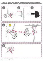
Страница 92: ...15 Attach the silica gel bag to the place indicated below and secure the housing cover using the torx wrench 60...
Страница 152: ...GV NVR Software DVD Warranty Card Note Power adapter can be purchased upon request 120...
Страница 168: ...Pan Adjustment Tilt Adjustment Rotational Adjustment 136...
Страница 179: ...Vandal Proof IP Dome Part II 15 15 2 Overview 1 2 3 4 5 6 8 7 9 10 12 11 13 14 147...
Страница 189: ...Vandal Proof IP Dome Part II 15 Pan Adjustment Tilt Adjustment Rotational Adjustment 157...
Страница 195: ...Vandal Proof IP Dome Part III 16 16 2 Overview 1 2 4 5 3 163...
Страница 207: ...Target Vandal Proof IP Dome 17 17 2 Overview 1 2 3 4 5 6 13 12 10 7 8 9 14 11 175...
Страница 225: ...Fixed IP Dome 18 Pan Adjustment Tilt Adjustment Rotational Adjustment 193...
Страница 230: ...15 Place the housing cover on the camera body with the GeoVision logo pointing toward the front of the camera 198...
Страница 243: ...Cube Camera 20 7 Adjust the angles of the camera based on live view and fasten the indicated screw 211...
Страница 253: ...PT Camera 22 22 2 Overview 1 2 3 4 5 6 7 8 9 10 11 12 221...
Страница 262: ...M3 Screw x 2 M2 Screw GV IPCAM Software DVD GV NVR Software DVD Warranty Card 230...
Страница 263: ...Pinhole Camera 23 23 2 Overview Camera Lens 1 2 3 4 Main Body 6 7 8 9 4 5 231...
Страница 279: ...Accessing the Camera 24 6 Unplug the Ethernet cable 247...
Страница 284: ...25 The Web Interface 1 2 3 4 5 6 7 8 9 10 11 12 13 252...