background image

Overview

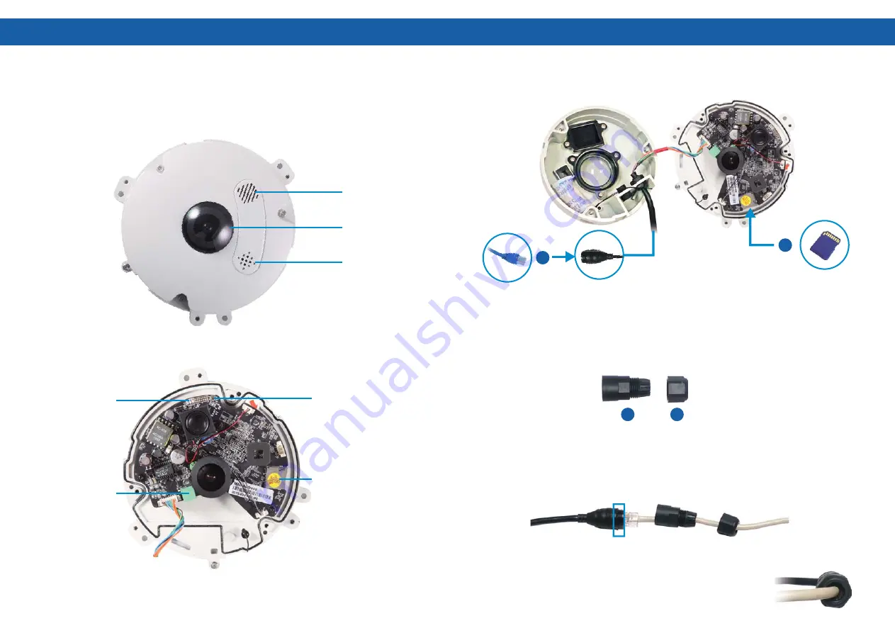
Connecting the Camera

Speaker

Microphone

Lens

Default Button

Micro SD Card Slot

LEDs

Power Terminal

Block

3

2

Rubber Seal Ring

A.  Prepare a network cable with the RJ-45 connector on one end only.
B.  Connect the network cable to the camera data cable. 
C.  Slide in the components through the end of the network cable without 

RJ-45 connector as shown below.

D.  Move the components toward the RJ-45 

connector, secure item 1 to the Rubber Seal 
Ring of the camera data cable and secure item 
2 to item 1 tightly.

1

2

1.  Remove the camera cover with the supplied torx wrench.
2.  Connect the camera to a Power over Ethernet (PoE) switch with a 

standard network cable to supply power and network. 
To waterproof the cable, you should have 2 components of the supplied 
cable connector:

Содержание GV-FE2302

Страница 1: ...n the connection to GV System GV VMS is interrupted Note for Recording 1 By default the images are recorded to the memory card inserted in the GV Fisheye IP Camera Make sure the Write recording data into local storage option is enabled If this option is disabled the camera will stop recording to the memory card while the live view is accessed through Web browsers or other applications For details ...

Страница 2: ...outage Use Micro SD card of MLC NAND flash Class 10 for better performance Note for Installing Camera Outdoor 1 The camera is set up above the junction box to prevent water from entering the camera along the cables 2 Any PoE power audio and I O cables are waterproofed using waterproof silicon rubber or the like 3 The screws are tightened and the cover is in place after opening the camera cover 4 A...

Страница 3: ...tion Sticker IR Power Adapter DC 12V 3 5A GV FER3403 5303 Power Adapter DC 12V 1 25A Note The power adapter DC 12V 1 25A can be excluded upon request Power Cable Waterproof Rubber Terminal Block x 2 Device TOP Device Device PoE Converter PoE Converter PoE Converter P o E C o n v e r te r IR female male GV Fisheye IP Dome Hardware Installation Guide GV NVR Software DVD GV NVR Quick Start Guide Cabl...

Страница 4: ...through the end of the network cable without RJ 45 connector as shown below D Move the components toward the RJ 45 connector secure item 1 to the Rubber Seal Ring of the camera data cable and secure item 2 to item 1 tightly 1 2 1 Remove the camera cover with the supplied torx wrench 2 Connect the camera to a Power over Ethernet PoE switch with a standard network cable to supply power and network T...

Страница 5: ...of the screws 2 Insert the power cable into the supplied female terminal block as illustrated and plug it into the terminal block connector in the camera 3 Connect the male terminal block on the power cable to female terminal block on the power adapter as illustrated below DC 12V Power Adaptor Terminal Block Female Terminal Block Connect to Camera Female Male Assembling the Power Adapter 3 Optiona...

Страница 6: ... holes 4 Secure the camera with the 3 hard ceiling mount screws provided 5 For the camera that does not come with an IR LED ring place the camera cover for hard ceiling mount on top of the camera and tighten the screws with the supplied torx wrench 6 Continued on the reverse A Secure the safety lock to the camera Then secure the camera cover B Place the IR LED ring on top of the camera and tighten...

Страница 7: ... part out of the ceiling Drill the 3 holes indicated as Device 1 In Ceiling Mount allows the GV Fisheye IP Camera to be mounted into the ceiling revealing a small portion of the camera In Ceiling Mount requires the ceiling board to be between 0 5 3 0 cm 0 2 1 18 in In Ceiling Mount Note In ceiling mount is not applicable to the models with IR LED ring GV FER3403 5303 Device TOP Device Device PoE C...

Страница 8: ...ws 5 Place the camera cover for in ceiling mount on top of the camera and put on the in ceiling cover 6 GV FE2302 3402 5302 and GV FE3403 5303 Packing List Camera Cover Hard Ceiling Mount Camera Cover In Ceiling Mount IR LED Ring GV FE3403 5303 Fisheye Camera PoE Converter set including 1 module 1 DC Power Y cable 1 RJ 45 cable and 3 screws GV FE3403 5303 only ...

Страница 9: ... PoE Converter PoE Converter PoE Converter P o E C o n v e r t e r IR Speaker Microphone Lens Rubber Bung Default Button Status LED Micro SD Card Slot Mini USB Slot Audio Out LAN PoE Power Terminal Block Overview GV IPCAM H 264 Software DVD GV Fisheye IP Dome Hardware Installation Guide GV NVR Software DVD GV NVR Quick Start Guide Note The power adapter can be excluded upon request ...

Страница 10: ...r to IR LED ring For installation steps see the next section Connecting PoE Converter and IR LED Ring for GV FE3403 5303 To install a PoE converter follow the steps below Note Instead of installing the PoE converter you can connect the camera to a PoE switch and the IR LED ring with a power adapter optional accessory separately PoE Converter PoE Switch 1 1 Connect the PoE converter to a PoE switch...

Страница 11: ...crews 5 Secure the PoE converter to the ceiling with 3 self prepared screws 20cm Installation Without IR LED Ring With IR LED Ring To install GV Fisheye Camera with PoE converter GV FE3403 5303 drill the 3 holes and the rectangle block indicated as PoE Converter Hard Ceiling Mount 2 1 Place the installation sticker on the ceiling board The 3 red dots indicate the location of the screws Device TOP ...

Страница 12: ...rovided Note Be sure to have the camera installed with the rubber bung to prevent the intrusion of any objects 3 Insert the 3 plastic screw anchors in the drilled holes 4 Secure the camera with the 3 hard ceiling mount screws provided 5 For the installation steps see In Ceiling Mount for GV FER3402 5302 and GV FER3403 5303 In Ceiling Mount Note In ceiling mount is not applicable to the models with...

Отзывы: