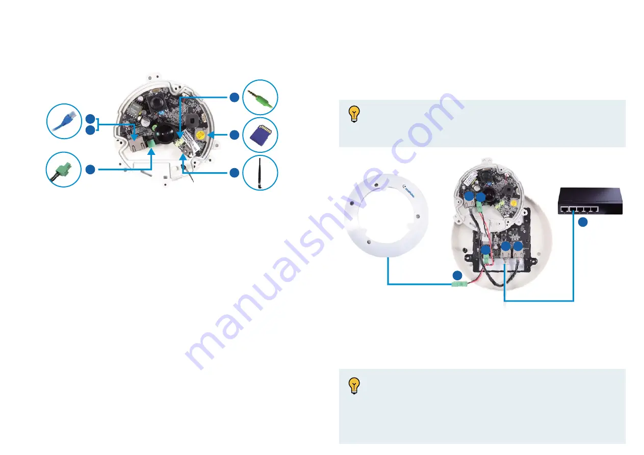
Connecting the Camera
2A
2B
2B
3
5
4
1. Remove the camera cover with the supplied torx wrench.
2. Supply power and network to the camera with one of the following
methods:
3. Optionally insert a micro SD card (SD/SDHC, version 2.0 only, Class 10).
4. Optionally connect an external speaker.
5. Optionally connect a GV-WiFi Adapter (for WiFi accessibility) or an
external USB hard drive (for additional storage).
6. Secure the camera cover with the supplied torx wrench.
A.
Power over Ethernet (PoE)
: connect the camera to a PoE switch
with a standard network cable to supply power and network.
B.
PoE Converter
: only for indoor cameras GV-FE3403 / 5303 installed
with an IR LED ring. A PoE converter allows the camera to be
connected to a PoE switch,and also supplies power to IR LED ring.
For installation steps, see the next section
Connecting PoE Converter
and IR LED Ring for GV-FE3403 / 5303
.
To install a PoE converter, follow the steps below.
Note:
Instead of installing the PoE converter, you can connect the
camera to a PoE switch and the IR LED ring with a power adapter
(optional accessory) separately.
PoE Converter
PoE Switch
1
1. Connect the PoE converter to a PoE switch with a standard network
cable. Use the RJ-45 connector on the left.
2. Connect PoE Converter and the camera with the supplied network cable.
Use the RJ-45 connector on the right.
Connecting PoE Converter and IR LED Ring for GV-FE3403 /
5303
PoE Converte
PoE converter to a PoE switch with a stan
e RJ 45
1
2
2
3
3
3
Camera
IR LED Ring
Note:
1. Due to limited space inside the PoE converter, use a standard
network cable without the rubber boot.
2. The camera will not work if you connect the wrong devices to
the two RJ-45 connectors on the PoE converter.


