30
3.
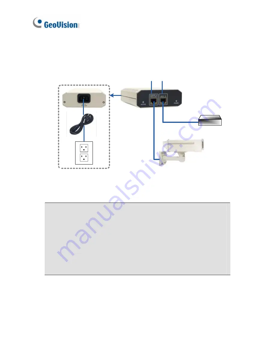
Optionally connect the camera’s cable to the GV-PA481 PoE adapter
as illustrated below. The power and network will be supplied
simultaneously.
Ethernet Cable
PoE
GV-BX-E
Rear Panel
Power
Hub/Router
POWER &
DATA OUT
DATA IN
4.
The status LED of the camera will be on.
Note:
For using the IR Arctic Box Camera, ensure that you:
1.
enable the IR LED
function on the Web interface after loading the
default settings.
2.
disable the status LED
to reduce reflection when a green light
spot appears on the live view.
For details, see
Notice for Using the IR Arctic Box Camera
section,
IR
Arctic Box Camera
Chapter,
GV-IPCam H.264 User’s Manual
on the
Software CD.
Содержание GV-CBW120
Страница 30: ...xxviii ...
Страница 120: ...Unscrew thread lock Unscrew the inner housing Take out the camera body 90 ...
Страница 134: ...11 2 Overview 1 2 3 4 5 6 8 7 9 10 12 11 13 104 ...
Страница 144: ...Tilt Adjustment Rotational Adjustment 114 ...
Страница 154: ...Pan Adjustment Tilt Adjustment Rotational Adjustment 124 ...
Страница 177: ...PT Camera 15 15 2 Overview 1 2 3 4 5 6 7 8 9 10 11 12 147 ...
Страница 188: ...4 The login page appears 5 Type the default ID and password admin and click Apply to log in 158 ...
Страница 194: ...6 Unplug the Ethernet cable 164 ...
Страница 198: ...168 Do not leave a distance between the Focus Adjustment Cap and the camera ...
Страница 199: ...17 The Web Interface 1 2 3 4 5 6 7 8 9 10 11 12 ...


