3
2
GV-Data Capture
GV-Data Capture
POS systems could come in different forms. In this manual, POS systems
are referred to those with receipt printers externally connected. Before
configuring, it is important to identify the interface type of your POS system.
It must be either serial or parallel.
POS System Connection
Our default settings are set to support serial POS systems, since most of
the POS systems available in market are serial. Follow these steps to
make the connection:
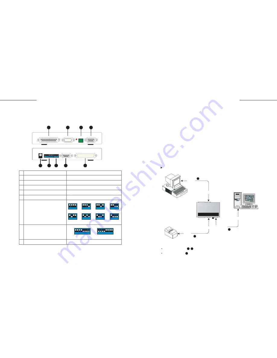
1. Connect the GV-Data Capture box as illustrated below:
POS System Using a DB9-D25 Cable
The RS-232 cables supplied with the GV-Data Capture box.
The RS-232 cable supplied with the POS system.
Serial POS System
The GV-Data Capture box is designed to connect a GV-system to a POS
system through PC COM ports.
GV-Data Capture
1 2 3 4 5 6 7 81 2 3 4
1
2
3
4
5
6
7
9
8
Note:
The default baud rate is set to 9,600 bps and the default DIP is set for the serial port.
1 25 pins parallel connector
Connects to a parallel printer
2 9 pins D-Sub male connector
Connects to a serial printer
3 2 pins RS-485 connector
Connects to the GV-NET box or GV-NET card
4 9 pins D-Sub RS-232 connector
Connects to a GV-system COM port
5 25 pins parallel connector
Connects to a parallel POS system
6 9 pins D-Sub female connector
Connects to a serial POS system
7 The 4-position baud-rate switch
settings are to configure the parallel
connection only. If you are using
a serial POS system, the settings
are not necessary.
8 The 8-position DIP switch settings
are to configure the serial or
parallel connection.
9 5V DC-IN
1 2 3 4
1,200 bps
1 2 3 4
1 2 3 4
1 2 3 4
1 2 3 4
1 2 3 4
1 2 3 4
1 2 3 4
2,400 bps
4,800 bps
9,600 bps
19,200 bps 38,400 bps 57,600 bps 115,200 bps
1 2 3 4 5 6 7 8
1 2 3 4 5 6 7 8
Parallel Port
Serial Port
DB25
Male
DB9 Female
GV-System
POS System
DB9
Female
DB9 Female
DB9 Male
DB9 Male
Printer
RS-232
2
2
1
3
RS-232
3
RS-232
1
GeoVision GV-DATA CAPTURE
Содержание DCV1-A-EN
Страница 1: ...2005 01 GV Data Capture...


