


19
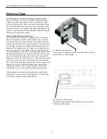
ECM Blower Control
The ECM blower motor is controlled by an interface board installed
in the air handler and allows field selectable CFM settings. The
interface board receives inputs from the thermostat and converts
them to signals used by the ECM motor. There are four different
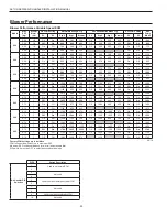
airflow settings that are field selectable via DIP switches (see
Blower Performance table).
Cooling/Heating settings
The cooling/heating CFM settings determine the normal cooling/
heating CFM when the unit is not in dehumidification mode or
auxiliary heat mode. DIP switches 1 and 2 ‘off’ is the lowest CFM
setting while with DIP switches 1 and 2 ‘on’ is the highest CFM
setting. To prevent air coil freeze up, the lowest CFM setting can
not be used when dehumidification mode is selected. DIP 9 must
be ‘on’ to enable normal airflow settings.
Dehumidification Mode settings
This setting provides for field selection of humidity control (via
setting DIP 9 ‘off’). The cooling airflow settings are determined by
the Cooling/Heating DIP switch settings above. Dehumidification
mode reduces the selected normal cooling CFM by 15%-20%
which increases the moisture removing capability of the heat pump.
To prevent air coil freeze up, the lowest CFM setting can not be
used when dehumidification mode is selected.
Dehumidification Mode (Continuous) – This mode is selected via
setting DIP 9 ‘off’ on the ECM interface board and will be engaged
whenever an ‘O’ input is present. In this mode any time the unit is
operating in cooling mode, it will run at a CFM level 15%-20% lower
than the selected normal cooling CFM.
NOTE:
Do not select dehumidification mode if the lowest Cooling/
Heating airflow level is selected (DIPS 1 & 2 off).
Auxiliary Heat settings - DIP 5 & 6 on the ECM interface board are
used to select the desired CFM in auxiliary/emergency heat mode.
Whenever auxiliary or emergency electric heat is energized this air
flow setting will be used.
ASTON SERIES AIR HANDLER INSTALLATION MANUAL