

13
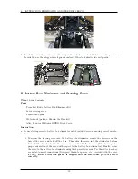
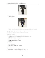
FRONT BRAKES, DISC ALIGNER
•
2 M3
×
50mm screws
•
2 M4
×
6mm screws (can use M4x14 from above and just pad with washers if needed)
•
4 M4
×
14mm screws (same as for the motherboard in the compute box)
•
4 M4 nuts
•
M4 washers
•
Throttle pivot set
•
Brake rod set
•
F 25 servo horn that came with the Baja (25 tooth for Futaba)
•
3 Bleed valve caps
•
1 Futaba J connector assembly (2 3x1 housings, 1 connector cover, 3 male 0.1 inch crimps, 3
female 0.1 inch crimps)
•
Servo Cable
•
Zip ties
•
Epoxy
Instructions
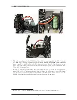
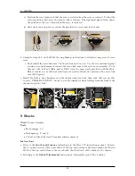
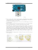
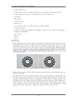
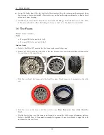
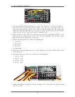
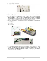
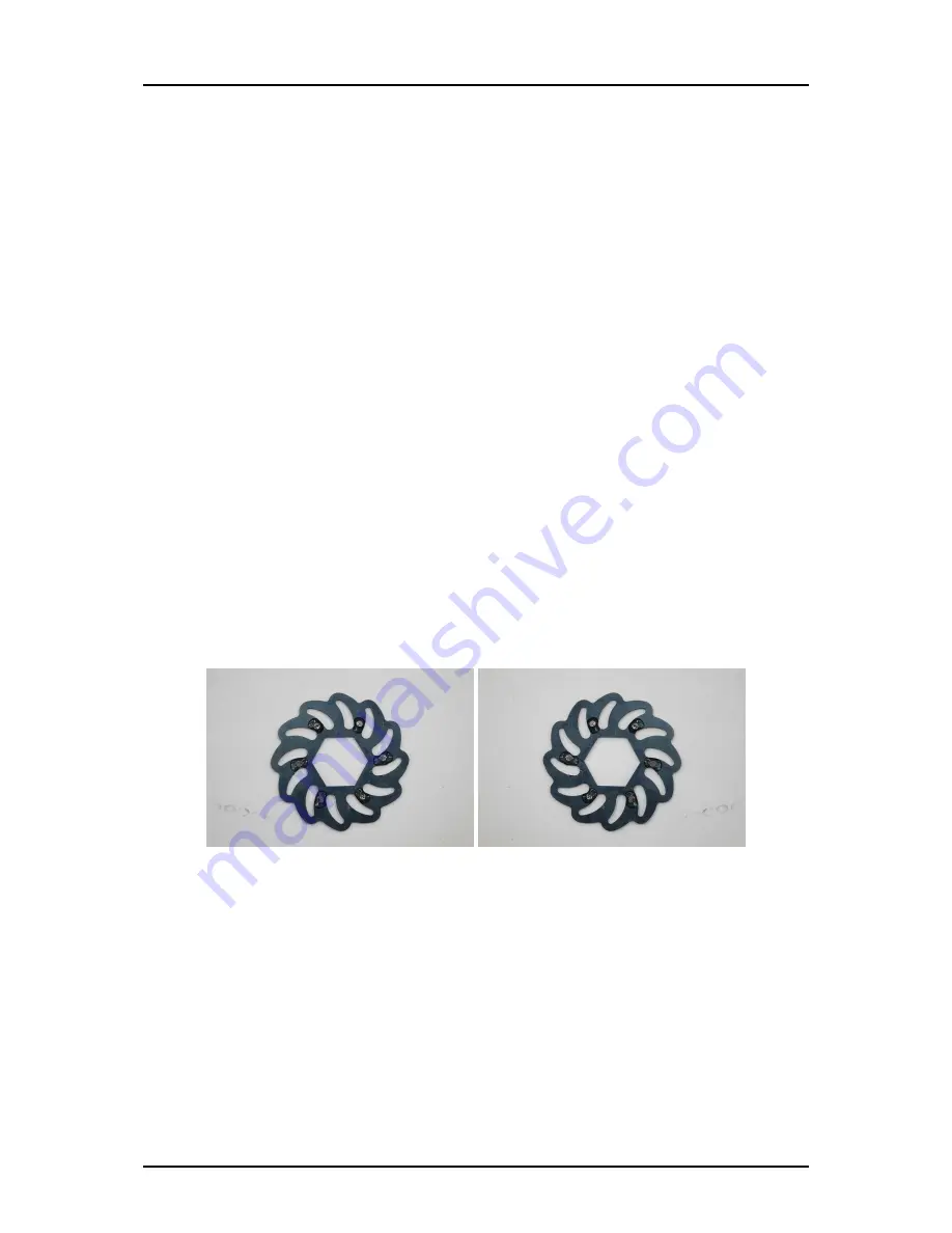
a. Epoxy 6 magnets to each of the brake discs such that the south pole of each magnet faces inward
towards the rotation sensor. To determine the south pole side of the magnet, use the test circuit
detailed in the previous section. The correct face is different for each brake disk, refer to the
pictures below (left disc shown on left, right disc shown on right).
Pay close attention to the
location of the magnets, as they must be aligned with the sensor but not interfere
with the brake caliper or the 3D printed front brake disk aligner.
Let the epoxy cure
for at least two hours.
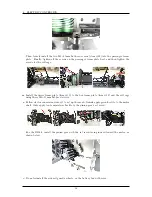
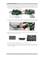
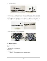
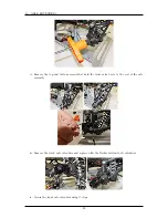
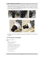
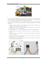
b. Remove the outtermost of the two M3
×
42mm screws from the top of each front hub carrier and
reserve for later use.
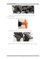
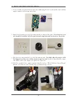
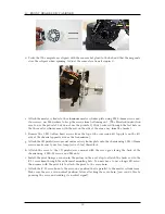
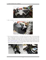
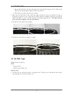
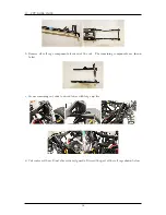
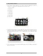
c. The disk caliper and caliper adjuster (provided in Mecatech kit) should be assembled first using
the M3 screws provided in th ekit. Slide the left and right brake discs onto the front axle
extenders with the magnets should be facing inward. Secure the brake caliper assemblies and
3D printed brake disc aligners onto the front wheel hubs with the reserved M3
×
42mm and a
M3
×
50mm screw. Once loosely attached, adjust the location of the disk aligner and the screws
on the calipers to allow the axles to spin freely. The hose plug on the caliper should be facing
upward on each side. For reference, the pictures shown below are for the left side.
29
Содержание AutoRally
Страница 1: ...AutoRally Chassis Instructions Version 1 4 June 2018 Georgia Institute of Technology...
Страница 2: ......
Страница 79: ...27 APPENDIX A PARTS Futaba FUTM1725 Charger for Futaba 4PV Glitch Capacitor GPS antenna 75...
Страница 80: ...27 APPENDIX A PARTS GPS antenna cable GPS box fan Hallogic OH090U Hall Effect sensors 76...
Страница 81: ...27 APPENDIX A PARTS Hemisphere GPS P307 Pololu Level Shifter Pololu RC Relay Pololu Servo Multiplexer 77...
Страница 82: ...27 APPENDIX A PARTS USB breakout board 27 6 Connectors 1 1 0 1 in header housing 1 2 0 1 in header housing 78...
Страница 88: ...27 APPENDIX A PARTS 1 M3 4mm screw 27 7 3 GPS Box 8 M3 8mm screws 4 M3 hex nuts 84...
Страница 89: ...27 APPENDIX A PARTS 2 M1 4 fan screws 2 M1 4 fan nuts 2 M3 25mm screws 85...
Страница 92: ......


