29
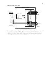
The figure below illustrates the DIP switch SW2 for switching between a GK-403 or Datalogger
application. “DATALOGGER”” is the default SW2 position:
GK-403/DATALOGGER Selection
F.2 MICRO-800/MICRO-1000 Mode of Operation
The MICRO-800 and MICRO-1000 (which respectively utilize a CR800 and CR1000 controller,
manufactured by Campbell Scientific, Inc. of Logan, Utah) mode of operation uses two control
lines to operate the multiplexer. The RESET line enables the multiplexer and activates the
MICRO-800/MICRO-1000 mode of clocking. Pulses received on the CLOCK line sequentially
increment the channels while the RESET line is held high. See the timing diagram below.
The CLOCK line sequentially advances the channels beginning with channel 1. Note the timing
diagrams below for 16 and 32 channel switching, respectively.
Reset
Clock
Channel 1
T1
T2
T3
No Channel
Selected
No Channel
Selected
Channel 16
Pulse 1
Pulse 2
Pulse 31
Timing:
T2 = 2 mSsec(min)
T3 = 2 mSsec(min)
T1 = 50 mSec(min.)
Selected
Selected
Pulse 32
16 Channel MICRO-800/MICRO-1000 Channel Selection Timing
GK-403
DATALOGGER
SW2

