background image

20 


S

AVE THE 

I

NCLUDE FILE IF MODIFIED


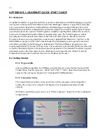
E.3.2 Uploading Files 

 
The Include.DLD file must be saved when modified. After modification, the 
Include.DLD must be sent to the Datalogger using the File Control Menu in the 
LoggerNet Connect Screen. The Main (.CR8/CR1) program file must be sent to the 
Datalogger each time the Include.DLD file is updated.  


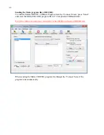
Sending the Include file (.DLD): 

From the “Connect Screen” press “File Control” and press “Send” to transfer the 
Include(.DLD) file to the Datalogger.  


N

OTE

:


E

ACH 

D

ATALOGGER HAS A UNIQUE 

I

NCLUDE

(.DLD)

 AND 

M

AIN

(.CR8/.CR1)

 FILE


Содержание 8025

Страница 1: ... means without the written consent of Geokon Inc The information contained herein is believed to be accurate and reliable However Geokon Inc assumes no responsibility for errors omissions or misinterpretation The information herein is subject to change without notification Copyright 2015 2017 by Geokon Inc Doc Rev L 3 12 18 ...

Страница 2: ......

Страница 3: ...re are no warranties except as stated herein There are no other warranties expressed or implied including but not limited to the implied warranties of merchantability and of fitness for a particular purpose Geokon Inc is not responsible for any damages or losses caused to other equipment whether direct indirect incidental special or consequential which the purchaser may experience as a result of t...

Страница 4: ......

Страница 5: ...s 7 A 1 4 Control Ports 8 A 2 AVW200 VIBRATING WIRE INTERFACE SEE AVW200 MANUAL FOR COMPLETE SPECIFICATIONS 8 A 3 MODEL 8032 MULTIPLEXER SEE THE APPENDIX F COMPLETE SPECIFICATIONS 8 APPENDIX B SHIP LIST 8 APPENDIX C DATA STORAGE 9 C 1 INPUT LOCATIONS 9 C 2 DATA STORAGE 9 C 3 DATA STORAGE EXAMPLE 10 APPENDIX D SYSTEM WIRING 11 D 1 CR800 WIRING 8025 2 8025 3 AND 8025 4 11 D 2 AVW200 WIRING 8025 2 80...

Страница 6: ... MODE OF OPERATION 29 F 3 WIRING 30 F 4 MODEL 8032 27 AND LOAD CELL WIRING 33 F 5 TROUBLESHOOTING 34 F 6 SPECIFICATIONS 34 F 6 1 General 34 F 6 2 Relays 34 F 6 3 Tripolar Plasma Surge Arrestor 35 F 6 4 Bipolar Plasma Surge Arrestor 35 F 6 5 Inductor 35 F 6 6 Transient Voltage Suppressor Transorb 35 F 6 7 Transducer Connection Maximum Operating Voltage Levels 35 F 6 8 Reset and Clock Maximum Operat...

Страница 7: ... Resource CD supplied with the datalogger A Campbell Scientific AVW200 Vibrating Wire Interface provides the required excitation and signal processing for the vibrating wire sensors connected to the Datalogger The AVW200 uses spectral analysis to find the resonant frequency of the Vibrating Wire Gage The AVW200 is also used to measure the thermistor used in Geokon s vibrating wire instruments For ...

Страница 8: ...ting dimensions shown in inches Figure 1 Dimensions 3 1 Turning on Power After the Datalogger is installed the charger can be plugged into the AC mains and the On Off switch S1 on the Charge Regulation circuit board switched to the On position Figure 2 It is recommended that the charger be left plugged in at all times Section 5 1 Figure 2 Charge Regulation Circuit Board ...

Страница 9: ...lease refer to Appendix F for the appropriate connection description 3 4 Communications Standard communications with the Datalogger is established by connecting the supplied serial cable to the RS 232 port Figure 3 and the COM port on a computer or a USB port on the computer by using the provided USB to Serial converter cable Figure 3 Datalogger Connections 4 SOFTWARE The Micro 800 Datalogger is o...

Страница 10: ...tery Additionally a large external battery such as a deep cycle marine battery may be connected to the Datalogger via the supplied external power cable to provide power to the Datalogger and peripherals When this type of battery is connected to the Datalogger the internal Datalogger battery is automatically disconnected from the system to prevent parasitic drain on the external battery 5 4 Battery...

Страница 11: ...g the communication port 4 The communication port on the host computer is defective Verify the functioning and configuration of the COM port by using it with another RS 232 device such as a modem or serial printer 5 The Datalogger Auxiliary Fuse on the Dual Mode Charger board is blown Refer to Appendix D 7 for proper fuse replacement The system battery voltage and panel temperature read odd number...

Страница 12: ...tting Section E 1 2 The cable s to the sensor s have been damaged permitting moisture and debris to enter the jacket Wires may be shorted together Inspect the cable 3 If all sensors on a particular multiplexer are erratic or returning 99999 perhaps the multiplexer or interface cable has been damaged unplugged 4 The sensor s have been damaged For example overrange on a vibrating wire sensor can cau...

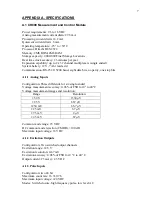
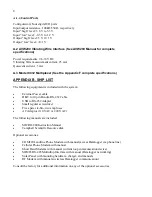
Страница 13: ...its no parity one stop bits A 1 1 Analog Inputs Configuration Three differential or six single ended Voltage measurement accuracy 0 06 of FSR for 0 to 40 C Voltage measurement ranges and resolution Range Resolution 5 0 V 1330 V 2 5 V 667 V 250 mV 66 7 V 25 mV 6 7 V 7 5 mV 2 V 2 5 mV 67 V Common mode range 5 VDC DC common mode rejection CMRR 100 dB Maximum input voltage 16 VDC A 1 2 Excitation Outp...

Страница 14: ... the system External Power cable DB 9 to 10 pin Bendix RS 232 Cable USB to RS 232 Adapter Small regular screwdriver Five spare slo blo two amp fuses AC Adaptor 110 VAC or 220 VAC The following manuals are included MICRO 800 Instruction Manual Campbell Scientific Resource disk Optional accessories COM220 Landline Phone Modem with manual access Datalogger via phone line Cellular Phone Modem with man...

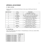
Страница 15: ...s from Start if Log selected as Scan Interval 8 ElapsdMin Elapsed Minutes from Start if Log selected as Scan Interval 9 ElapsdSec Elapsed Seconds from Start if Log selected as Scan Interval 10 Battery Datalogger battery voltage 11 PanelTemp Datalogger panel temperature C 47 78 Mx1 Readings from Gages on Mux 1 C 2 Data Storage Total Arrays of Data that can be stored per 16 Channel Multiplexer Each ...

Страница 16: ...ultiplexer Overwrite Time 735 407 12 256 8 510 7 12 257 3 Multiplexer Overwrite Time 521 196 8 686 6 361 9 8 686 4 Multiplexer Overwrite Time 403 022 6 717 0 279 9 6 701 5 Multiplexer Overwrite Time 327 413 5 456 9 227 4 5 457 6 Multiplexer Overwrite Time 275 573 4 592 9 191 4 4 593 If data is stored once a day Minutes Hours Days Total Arrays 1 Multiplexer Overwrite Time 29 795 034 496 583 9 20 69...

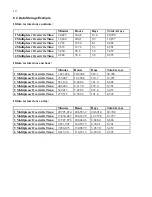
Страница 17: ...ions Color MUX Interface Ribbon Cable CR800 Datalogger Description 1V Brown Conductor 1 NC Vibrating Wire 1V Red Conductor 2 NC Vibrating Wire 1T Orange Conductor 3 NC Thermistor 1T Yellow Conductor 4 NC Thermistor SCI12 Blue NC C3 SDI 12 Communications G Blue s Black NC G Ground 12V Red NC 12V 12VDC Power G Red s Black NC G Ground D 3 CR800 Wiring 8025 5 CR800 Connections MUX 1 Interface Cable MU...

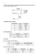
Страница 18: ...TS E Blue CTS G Violet DTR D 5 Charger Wiring Pin Description Wire Color A Charger 14 22 VDC Input Grey B Ground Blue C Battery 12 VDC Output Violet D 6 Cables D 6 1 AC Charger 110VAC 220VAC Pin Description Condor Wire Color A Charger 14 22 VDC Input Black with White Stripe B Ground Black D 6 2 External Power Cable Pin Description Wire Color Clip A No Connection No Connection No Connection B Groun...

Страница 19: ... 3 F4 External Battery F5 Battery D 8 Multiplexer Connector Wiring 10 Pin Bendix Color Description A Brown Vibrating Wire B Red Vibrating Wire C Orange Thermistor D Yellow Thermistor E Green Analog Ground F Blue 12 VDC G Violet Ground H Grey MUX Reset J White MUX Clock K Black Analog Ground ...

Страница 20: ...all programming code required to read and store Data according to the Datalogger configuration The Main CRBasic program does not require modification by the user in most cases The second file is the Include DLD text file and is used by the Main program to import user specific parameters The Include File allows program parameters such as the Scan Interval Zero Readings Linear Gage Factors Data File...

Страница 21: ... Std View icon at the top right of the Setup Screen This Quick Start will show the Std View of the Setup Screen To add a communication port press Add Root button Each Datalogger will communicate via RS232 Select connection type ComPort PakBusPort Other Loggers CR1000 or CR800Series and press Close ...

Страница 22: ...ABLED TO OPEN THE COMMUNICATIONS PORT COM NUMBERS VARY WITH COMPUTER USB DEVICES AND SERIAL ADAPTERS REFER TO THE COMPUTER DEVICE MANAGER IF UNSURE OF WHICH COM NUMBER TO USE Select PakBusPort under the Network Map in Maximum Baud Rate for direct connection to the Datalogger select 115200 WHEN FINISHED PRESS THE APPLY BUTTON AT THE BOTTOM LEFT OF THE SETUP SCREEN TO SAVE ALL SETTINGS ...

Страница 23: ...17 E 2 3 Connecting to the Datalogger With the LoggerNet Launch Menu open hover over Main and press Connect Select the Datalogger to communicate with under Stations and press the Connect button ...

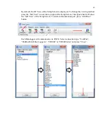
Страница 24: ... ONLY CHANGE VALUES AFTER THE SIGN E 3 1 Editing the CRBasic Program Scan Interval The number entered in the Scan Interval section determines how often the Datalogger will read the gages and store data The Scan Interval is in seconds Zero Readings Gage Factors Default values for Zero Readings are 0 and Linear Gage Factors are 1 The default settings read in Digits for Vibrating Wire sensors and Vol...

Страница 25: ...s for Temperature Zero Readings and Thermal Factors are 0 Temperature Zero Readings and Thermal Factors can be added if the user requires the Datalogger to use temperature compensation Navigate to the Main CR8 CR1 file C Campbellsci CRBasicEditor Open the Main CR8 CR1 file with notepad and uncomment the line specified in the code for all model gages that temperature correction is required Output L...

Страница 26: ...ger using the File Control Menu in the LoggerNet Connect Screen The Main CR8 CR1 program file must be sent to the Datalogger each time the Include DLD file is updated Sending the Include file DLD From the Connect Screen press File Control and press Send to transfer the Include DLD file to the Datalogger NOTE EACH DATALOGGER HAS A UNIQUE INCLUDE DLD AND MAIN CR8 CR1 FILE ...

Страница 27: ...21 Select DLD file type to make the Include DLD file visible in C Campbellsci CRBasicEditor Uncheck Run Now the Include DLD file cannot run the Datalogger ...

Страница 28: ...ram from the Connect Screen press Send and select the Main CR8 CR1 program file in C Campbellsci CRBasicEditor NOTE EACH DATALOGGER HAS A UNIQUE INCLUDE DLD AND MAIN CR8 CR1 FILE When sending the Main CR8 CR1 program file through the Connect Screen the program runs automatically ...

Страница 29: ...ame button Renaming the Datalogger affects the name of the Data file Output File Name option allows changing the file name where to collect and store the Data file File Output Option determines whether new Data collected is appended into one file overwrites old Data or creates a new file every time Data is collected COLLECTED DATA TABLES ARE SIGNIFIED WITH A GREEN CHECK MARK WHEN FINISHED PRESS TH...

Страница 30: ...er Main and press Connect Once the program is running most current readings can be viewed under Table1 of the Table Monitor and Num Display Graphs can also be used to view live and historical Data CONDITIONAL NOTE IT MAY BE NECESSARY TO START MONITORING BY PRESSING START ...

Страница 31: ...ng Data Pressing Collect Now collects and stores Data on the computer After collecting Data a Data Collection Results screen will open PLEASE SEE LOGGERNET MANUAL FOR MORE SPECIFIC DETAILS REGARDING USE OF THE SOFTWARE ...

Страница 32: ...Terminal Board only typically used in conjunction with a 4999 Manual Switch Box 8032 C Terminal Board with Multiplexer typically used with the Micro 800 Datalogger MICRO 1000 Datalogger or GK 403 Readout Box Two switching configurations are supported 16 channels of four conductors or 32 channels of two conductors For the 8032 C these configurations are set by a DIP switch on the top side of the ci...

Страница 33: ...or 16 Sensor Shield 1H 2H 1L 2L S1 31H 32H 31L 32L S16 16 Channel Switching Block Diagram The 16 channel four wire switching configuration is typically used to multiplex four wire sensors such as resistance strain gage load cells It is also used to switch connections for instruments which have more than one sensor integral to them such as vibrating wire pressure transducers with an integral thermi...

Страница 34: ...thermocouples The multiplexer is powered by a nominal 12 VDC supply Two control lines RESET and CLOCK determine how channel selection is accomplished Two schemes are supported one when connected to the GK 403 Vibrating Wire Readout Box and the other when connected to MICRO 800 or MICRO 1000 dataloggers See the following sections explaining how each mode operates The figure below illustrates the DI...

Страница 35: ...T line enables the multiplexer and activates the MICRO 800 MICRO 1000 mode of clocking Pulses received on the CLOCK line sequentially increment the channels while the RESET line is held high See the timing diagram below The CLOCK line sequentially advances the channels beginning with channel 1 Note the timing diagrams below for 16 and 32 channel switching respectively Reset Clock Channel 1 T1 T2 T...

Страница 36: ...nal Board Vibrating Wire with Thermistor Resistance Strain Gage Bridge Linear Potentiometer with Remote Sense 1H VW Sensor 1 S from Bridge 1 Excitation Pot 1 1L VW Sensor 1 S from Bridge 1 Wiper Output Pot 1 2H Thermistor 1 P to Bridge 1 Remote Sense Pot 1 2L Thermistor 1 P to Bridge 1 Ground Pot 1 S1 Shield Drain Wire from Sensor 1 Shield Drain Wire from Bridge 1 Shield Drain Wire from Pot 1 3H V...

Страница 37: ...Sensor 3 Thermistor 3 Thermocouple 3 3L VW Sensor 3 Thermistor 3 Thermocouple 3 4H VW Sensor 4 Thermistor 4 Thermocouple 4 4L VW Sensor 4 Thermistor 4 Thermocouple 4 S2 Shield Drain Wires from Sensors 3 4 Shield Drain Wires from Thermistors 3 4 31H VW Sensor 31 Thermistor 31 Thermocouple 31 31L VW Sensor 31 Thermistor 31 Thermocouple 31 32H VW Sensor 32 Thermistor 32 Thermocouple 32 32L VW Sensor ...

Страница 38: ... J2 1H 1L 2H 2L S1 3H 3L 4H 4L S2 5H 5L 6H 6L S3 7H 7L 8H 8L S4 9H 9L 10H 10L S5 11H 11L 12H 12L S6 13H 13L 14H 14L S7 15H 15L 16H 16L S8 17H 17L 18H 18L S9 19H 19L 20H 20L S10 21H 21L 22H 22L S11 23H 23L 24H 24L S12 25H 25L 26H 26L S13 27H 27L 28H 28L S14 29H 29L 30H 30L S15 31H 31L 32H 32L S16 J EARTH J4 T1 2 T3 4 T5 6 T7 8 T9 10 T11 12 T13 14 T15 16 T17 18 T19 20 T21 22 T23 24 T25 26 T27 28 T29...

Страница 39: ...2 10P Function 3 Gage VW Load Cell Purple Cable 4 Gage VW Load Cell Purple Cable 6 Gage VW Load Cell Orange Cable H Common White s Black Green Blue White s black and Green wires are switched on Geokon three gage VW load cells prior to serial number 3313 Common Conductor Chart The following wiring chart details the connections between the load cell and 8032 27 with the multiplexer board Multiplexer...

Страница 40: ...selection appears to be random Has corrosion built up on the circuit board Clean if necessary Is there a source of electrical noise nearby Move multiplexer or noise source if possible F 6 SPECIFICATIONS F 6 1 General Power Requirements 10 16 VDC unregulated Quiescent Current MICRO 800 MICRO 1000 mode 80 A 16CH mode 130 A 32CH mode Quiescent Current GK 403 mode 12 mA Channel Activated Current 30 mA...

Страница 41: ...Arrestor Nominal DC Breakdown Voltage 150V Maximum Surge Current 1 kA 8 20 s pulse Insulation Resistance 1010 Operating Temperature 65 to 125 C F 6 5 Inductor Rated Current 4A Inductance 10µH 20 D C R 25m MAX at 20 C F 6 6 Transient Voltage Suppressor Transorb Rated Power 1500W Peak forward Surge Current 200A Reverse Standoff Voltage 16 0V F 6 7 Transducer Connection Maximum Operating Voltage Leve...

Страница 42: ...on 8032 5 TAN Cable Wire Color 1 2 SHLD SHIELD Shield Drain Wires all pairs plus overall 3 4 SHLD SHIELD Shield Drain Wires all pairs plus overall 5 6 C1H COM HI 1 White 7 8 C1L COM LO 1 White s Black 9 10 C2H COM HI 2 16 channel Red 11 12 C2L COM LO 2 16 channel Red s Black 13 14 SHLD SHIELD Shield Drain Wires all pairs plus overall 15 16 12V 12 Volt Power Yellow 17 18 GND Power Ground Yellow s B...

Страница 43: ... Setting Channels Accessed 2 3 4 OFF OFF OFF 1 32 32 channel mode 1 16 16 channel mode DEFAULT MUX1 OFF OFF ON 33 64 32 channel mode 17 32 16 channel mode MUX2 OFF ON OFF 65 96 32 channel mode 33 48 16 channel mode MUX3 OFF ON ON 97 128 32 channel mode 49 64 16 channel mode MUX4 ON OFF OFF 129 160 32 channel mode 65 80 16 channel mode MUX5 ON OFF ON 161 192 32 channel mode 81 96 16 channel mode MU...

Страница 44: ... C7 C8 Multiplexer 1 MUX1 Reset Clock Reset Reset Clock Clock Multiplexer 2 MUX2 Multiplexer 3 MUX3 H J H H J J VW Gages 1 32 VW Gages 65 96 VW Gages 33 64 H J H J IN IN IN OUT OUT SW1 SETTING 2 3 4 OFF OFF OFF SW1 SETTING 2 3 4 OFF OFF ON SW1 SETTING 2 3 4 OFF ON OFF ...

Страница 45: ... number of 8032 Multiplexers Daisy Chain configuration and system battery voltage need to be considered in determining the maximum 8032 5 cable length For a single 8032 Multiplexer under normal operating conditions System Battery 12V ambient temperature 20 C the maximum recommended cable length from the Datalogger to the 8032 Multiplexer is 4588 feet 1400m The chart below displays the maximum reco...

Страница 46: ...e Shield Up to eight Biaxial MEMS sensors are connected to each Canary six wire Multiplexer through the weather tight strain relief fittings mounted to the Datalogger enclosure with the final connection made to the terminal blocks mounted on the Multiplexer Each terminal block or Multiplexer channel consists of seven clamp connections A sample biaxial MEMS connection is as follows for terminal blo...

Отзывы: