background image

Air Handler

16

4.9.2 Wire Sizing 

Wire size is important to the operation of your equipment. Use the following check list when 

selecting the appropriate wire size for your unit. 

Wire size must carry the Minimum Circuit Ampacity (MCA).

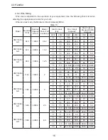
Table 13

Model

Nominal 

CFM

Nominal 

Capacity 

BTU/H

Blower 

Motor Full 

Load Amps

Electric Heat

(kw)

Min. Circuit

Ampacity*

Max. Fuse or 

Breaker(HACR)

Ampacity

240V

208V

240V

208V

240V

208V

HNF13018/

A-D

640

18000

0.62

0

0

0.65

0.65

15

15

5

3.8

26.8

23.3

30

25

10

7.5

52.9

45.9

60

50

HNF13024/

A-D

825

24000

1.52

0

0

1.9

1.9

15

15

5

3.8

26.9

23.4

30

25

10

7.5

52.9

45.9

60

50

HNF13030/

A-D

980

30000

1.25

0

0

1.7

1.7

15

15

5

3.8

27.6

24.1

30

25

10

7.5

53.6

46.7

60

50

15

11.3

53.6/26 46.7/23

60/30

50/25

HNF13036/

A-D

1140

36000

2

0

0

2.5

2.5

15

15

5

3.8

28

24.4

30

25

10

7.5

54

47

60

50

15

11.3

54/26

47/22.5

60/30

50/25

20

15

54/52.1 47/45.1

60/60

50/50

HNF13042/

A-D

1350

42000

2

0

0

2.5

2.5

15

15

5

3.8

28.1

24.6

30

25

10

7.5

54.2

47.1

60

50

15

11.3

54.2/26 47.1/22.5 60/30

50/25

20

15

54.2/52.1 47.1/45.1 60/60

50/50

HNF13048/

A-D

1400

48000

2.5

0

0

3.1

3.1

15

15

5

3.8

29.3

25.8

30

30

10

7.5

55.3

48.3

60

50

15

11.3

55.3/26 48.3/22.5 60/30

50/25

20

15

55.3/52.1 48.3/45.1 60/60

50/50

HNF13060/

A-D

1650

60000

4.6

0

0

5.8

5.8

15

15

5

3.8

31.8

28.6

35

30

10

7.5

57.8

50.8

60

60

15

11.3

57.8/26 50.8/22.5 60/30

60/25

20

15

57.8/52.1 50.8/45.1 60/60

60/50

Содержание HW(R)130

Страница 1: ...e read this Installation manual carefully before operation and retain it for future reference GENEX reserves the right to interpret this manual which will be subject to any change due to product impro...

Страница 2: ......

Страница 3: ...lation 5 3 1 Pre Installation Instruction 5 3 2 Important Safety Instructions 5 4 Installation 7 4 1 Unit Inspection 7 4 2 Location 7 4 3 Piping Work 8 4 4 Special Instructions 9 4 5 Drain Pan Refit 1...

Страница 4: ...Malfunction and Elimination 24 7 Maintenance and Care 25 7 1 Outdoor Heat Exchanger 25 7 2 Drain Pipe 25 7 3 Notice before Seasonal Use 25 7 4 Maintenance after Seasonal Use 26 7 5 Parts Replacement 2...

Страница 5: ...National Electrical Code NEC for special requirements Recognize safety information This is the safety alert symbol When you see this symbol on the unit and in instructions or manuals be alert to the p...

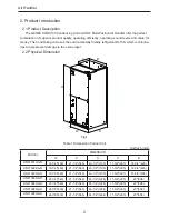
Страница 6: ...layer 2 2 Physical Dimension A B D W H Fig 1 Table 1 Dimension of Indoor Unit Unit Inch mm MODEL DIMENSION W D H A B HNF13018 A D 18 1 8 460 21 1 4 540 43 1 2 1105 11 5 8 295 16 3 4 426 HNF13024 A D 1...

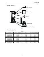
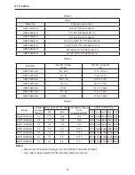
Страница 7: ...Primary Drain Pan Fig 2 2 4 General Information Table 2 Model No Cooling Capacity SCFM Electric Heater kw HNF13018 A D 1 5 Ton 640 0 10 HNF13024 A D 2 0 Ton 825 0 10 HNF13030 A D 2 5 Ton 980 0 15 HNF1...

Страница 8: ...72 147 7 158 8 HNF13048 A D 79 84 174 2 185 2 HNF13060 A D 80 86 176 4 189 6 Table 5 Model Airflow Tonnage Range Motor 230V 1Ph 60Hz DD Blower Wheel inch Diameter Width SCFM vs ESP 1 2 HP FLA 0 1 0 2...

Страница 9: ...ement Parts When reporting shortages or damages or ordering repair parts give the complete product model and serial numbers as stamped on the product Replacement parts for this product are available t...

Страница 10: ...performed in accordance with the national electric code nec american national standards institute ansi national fire protection association nfpa 70 and local state codes In canada electric grouding c...

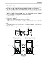
Страница 11: ...ler is designed for indoor installation only Do not install it outdoors When installing the air handler take consideration to minimize the length of refrigerant tubing as much as possible Do not insta...

Страница 12: ...D 7 8 3 8 HNF13048 A D 7 8 3 8 HNF13060 A D 1 1 8 1 2 4 3 2 Piping Preparation All cut ends are to be round burr free and cleaned Failure to follow this practice increases the chances for refrigerant...

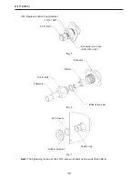
Страница 13: ...1 4 4 Special Instructions This air handler comes with a plastic accessory bag which contains tailpiece and white teflon seal WARNING The coil is shipped under pressure Release the pressure before ins...

Страница 14: ...3 16 NUT 9 16 NUT Schneider valve and white teflon seal Fig 5 Flowrator Piston 13 16 NUT Tailpiece White teflon seal Fig 6 Cap closure Rubber grommet Suction line Fig 7 Note The tightening torque of t...

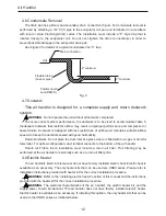
Страница 15: ...sides 1 Disassemble the front panel 2 Remove the mounting plate used to fix the drain pan from chassis And dismantle the enhanced frame if applicable 3 Pull out the evaporator coil and the drain pan i...

Страница 16: ...ains suitable airflow speed And keep the ductwork sealed with good hermeticity Return Ductwork Do not place the duct inlet at a place where is filled with toxic gas or harmful fume odor For upflow con...

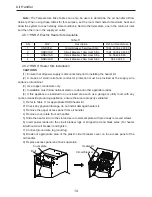
Страница 17: ...A 800 20 40 N A N A 1000 16 32 48 N A 1200 13 27 40 53 1400 11 23 34 46 1600 10 20 30 40 1800 9 18 27 36 220 1 60 Supply Voltage Temperature Rise Table F Table 10 CFM HEATER KIT NOMINAL KW 5 10 15 20...

Страница 18: ...ef and conductor protection must be provided at the supply wire entrance into cabinet 3 Use copper conductors only 4 Installation must follow national electric code and other applicable codes 5 If thi...

Страница 19: ...he grounding piece located in the unit control box and also connecting to the building electric service panel Other methods of grounding are permitted if performed in accordance with the national elec...

Страница 20: ...9 60 50 HNF13030 A D 980 30000 1 25 0 0 1 7 1 7 15 15 5 3 8 27 6 24 1 30 25 10 7 5 53 6 46 7 60 50 15 11 3 53 6 26 46 7 23 60 30 50 25 HNF13036 A D 1140 36000 2 0 0 2 5 2 5 15 15 5 3 8 28 24 4 30 25 1...

Страница 21: ...OP 4 9 4 Electric Connections Supply Voltage Use Copper Conductors Only a knockout is provided on the air handler top panel or side to allow for the entry of the supply voltage conductors If the knock...

Страница 22: ...24RD BLOWER MOTOR XFMR YE WH 1RD 2WH 4RD 5RD 6RD 9RD 10RD 11RD MAIN BOARD 7RD 8WH SEE NOTE 1 O 12RD SEE NOTE 4 SEE NOTE 5 X10 X3 C G_SCAN 3RD X8 AC L X1 AC N X2 FU2 RD BK 1 BU SEE NOTE 3 X7 N X13 L X1...

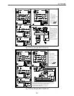
Страница 23: ...al for 230 volts tape seal the unused blue lead POWER RD 31 GROUND BK BK BK BK 32 3 1 6 5 4 3 2 1 L2 L1 X1 RD RD 33 31 GROUND BK BK BK BK BK BK 4 3 2 1 6 5 4 3 2 1 L1 X1 XT3 G R asda Fig 11 Wiring Dia...

Страница 24: ...W2 W1 G R POWER C M XT1 13YEGN O_SCAN GROUND X9 X4 R L1 L2 RD 31 GROUND BK BK BK BK 32 3 1 L2 L1 Fig 13 Wiring Diagram HNF13036 A D Notes HEAT STRIP 4 LS1 4 HS 2 CB2 CB2 HEAT STRIP 3 LS1 3 HS 2 HEAT...

Страница 25: ...If you ordered the Heat kit without circuit breaker connect the supply power to the stripped black and red wires O C W2 W1 R O_SCAN X9 X4 R Fig 15 Wiring Diagram HNF13048 A D 1 For Air Handler withou...

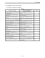
Страница 26: ...r Handler 22 4 9 6 Thermostat Wiring Fig 17 Fig 18 Note The signal line of the wired controller must be separated from the power line and the connecting line between the indoor unit and the outdoor un...

Страница 27: ...rts might be burned Check if the wiring and pipe line has been installed correctly Malfunction might happen and parts might be burned Check if the unit has been earthed soundly Hazard of electricity l...

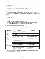
Страница 28: ...eral modes and check if the unit operates normally 6 Common Malfunction and Elimination If the unit doesn t run normally please check the following items before ask for service Table 16 Phenomenon Rea...

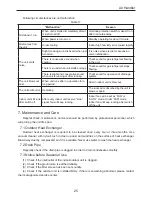
Страница 29: ...ng The room odor absorbed by the unit is blew out again Indoor unit still runs after switch off After every indoor unit receive stop signal fan will keep running Indoor fan can be set as FAN or AUTO m...

Страница 30: ...cessary 8 After Sales Service In case the air conditioning unit you bought has any quality problem or you have any inquiry please contact the local after sales service agency designated by factory War...

Страница 31: ......

Страница 32: ......

Отзывы: