Model FL3102
Quick Start Guide
ix
Normally de-energized
TB2, Term 6 = WARN 1 = Normally Closed
TB2, Term 7 = WARN 2 = Normally Open
Normally energized
TB2, Term 6 = WARN 1 = Normally Open
TB2, Term 7 = WARN 2 = Normally Closed
The WARN relay contact ratings are 8A @ 250VAC and 8A @ 30VDC.
CAUTION –
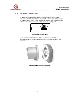
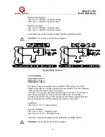
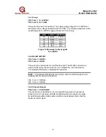
For all relay connections see Figure 9.
Figure 9 Relay Contacts
1.4.3 Fault Relay
TB2, Term 8 = FLT C
TB2, Term 9 = FLT 1
TB2, Term 10 = FLT 2
Description: These connections are to the SPDT FAULT relay. The FAULT
output configuration is normally energized and non-latching. This is the standard
output configuration and it cannot be changed.
The FAULT circuit will be activated during the time-out function, a low power or
loss of power condition, and during a failed COPM check. During these
conditions, the FAULT relays will de-energize and the analog output signal will
drop to 0 mA (2mA for COPM Faults) for the duration of the FAULT.
Fault Relay:
TB2, Term 8 = FLT C = Fault Common
Normally energized
TB2, Term 9 = FLT 1 = Normally Open
TB2, Term 10 = FLT 2 = Normally Closed
The FAULT relay contact ratings are 8A @ 250VAC and 8A @ 30VDC.
CAUTION –
For all relay connections see Figure 9.


