background image

General Dynamics


4096-387 

SATCOM Technologies 

1.2M Ku-BAND Rx/Tx SERIES 1123 


SECTION II   

ANTENNA SYSTEM ASSEMBLY 


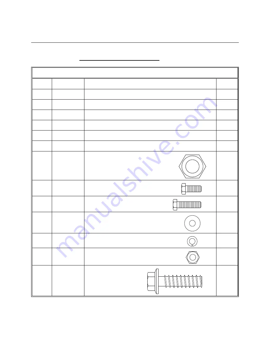
REFLECTOR AND SUPPORT ASSEMBLY PART LIST- TABLE 2.0


ITEM 


PART NO. 


DESCRIPTION QTY 


0181-585 

 
Canister Assembly 


0181-399 

 
Mount Assembly 


VARIES 

 
1.2M Reflector 


0156-572 

 
Elevation Marking Plate                                                   


0211-552 

 
Elevation Indicator 


8115-003 

 
1/2” Coupling Nut 


8104-007 


8302-006 


8302-004 


10 


8201-037 


11 


8202-032 


12 


8111-005 


13 


8319-006 


Hi-Lo Screw   

1/2” Hex Nut 

#10 x .50 Screw 

#10 x .75 Screw 

#10 Flatwasher 

#10 Lockwasher 

#10 Hex Nut

Содержание 1123 series

Страница 1: ...387 Revision E April 20 2016 ASSEMBLY MANUAL 1 2M Ku BAND Rx Tx SERIES 1123 ANTENNA SYSTEM General Dynamics SATCOM Technologies 1700 Cable Drive NE Conover NC 28613 USA Phone 770 689 2040 www gdsatcom...

Страница 2: ...Conover Address 4 19 16 RAH D Revised Company Name Logo and Part Tables 7 13 09 RAH C Revised Address 1 11 02 RAH B Revise per canister assembly 3 23 98 PGW A Revise and Update 3 6 98 PGW ORIGINAL RE...

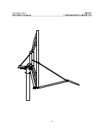
Страница 3: ...General Dynamics 4096 387 SATCOM Technologies 1 2M Ku BAND Rx Tx SERIES 1123 2...

Страница 4: ...OR DAMAGED 1 4 MECHANICAL INSTALLATION TOOLS 1 5 SITE SELECTION 1 6 FOUNDATION INTERFACE II ANTENNA SYSTEM ASSEMBLY 2 0 REFLECTOR SUPPORT ASM PART LIST 2 1 ANTENNA ASSEMBLY III FEED SUPPORT ASSEMBLY...

Страница 5: ...on on antenna alignment to the satellite and maintenance 1 1 UNPACKING AND INSPECTION The system containers should be unpacked and inspected at the earliest date to insure that all material has been r...

Страница 6: ...for installation Inclinometer Compass Adjustable Wrench Screw Driver standard blade 1 5 SITE SELECTION In order to achieve maximum performance of your antenna system it is important to select the cor...

Страница 7: ...7 3 Soil bearing capacity should be no less than 2000 PSF 4 Concrete should be poured against undisturbed soil 5 Allow concrete 24 hours set time before installation of antenna 6 The antenna should be...

Страница 8: ...RIPTION QTY 1 0181 585 Canister Assembly 1 2 0181 399 Mount Assembly 1 3 VARIES 1 2M Reflector 1 4 0156 572 Elevation Marking Plate 1 5 0211 552 Elevation Indicator 1 6 8115 003 1 2 Coupling Nut 1 7 8...

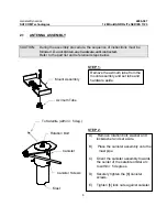
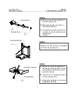
Страница 9: ...STEP 1 STEP 2 Remove the azimuth tube from the mount assembly and set tube and hardware aside Mount Assembly Azimuth Tube A Remove rotation bolt washer and lockwasher and set aside B Place the caniste...

Страница 10: ...tem 7 onto the azimuth rod to hold the tube in place Azimuth Rod Nut Azimuth Tube Nut 7 Thread a 1 2 hex nut item 7 a distance of 6 onto the elevation rod A Maneuver the mount assembly so that the end...

Страница 11: ...urely but DO NOT over tighten as this may cause damage to the reflector Mount Assembly Feed Rod Hole Feed Rod Hole A Place the reflector mount assembly step 6 onto the canister assembly B Secure the r...

Страница 12: ...vation indicator to the bottom plate of the mount assembly with 10 hardware items 8 10 11 10 12 9 10 11 Elevation Marking Plate Elevation Indicator A Adjust azimuth tube so that the tube will fit into...

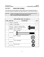
Страница 13: ...ng the assembly procedure the sequence of instructions must be followed Do not tighten any hardware until instructed Refer to the part list and referenced steps below FEED SUPPORT PART LIST TABLE 3 0...

Страница 14: ...LIST CONTINUED ITEM PART NO DESCRIPTION QTY 8 8030 008 2 9 8201 040 4 10 8202 040 2 11 8100 007 2 3 1 FEED SUPPORT ASSEMBLY STEP 1 1 4 Flatwasher 1 4 Lockwasher 1 4 Hex Nut 1 4 x 1 00 Bolt A Attach f...

Страница 15: ...ith Hi Lo screw item 3 See Detail D C Tighten the hardware at the reflector rim snug details A D Do Not over tighten as this can cause damage to the reflector D Next tighten the 5 16 hardware and then...

Страница 16: ...nologies 1 2M Ku BAND Rx Tx SERIES 1123 15 3 Reflector Feed Rod DETAIL A 9 10 11 Feed Support Feed Support Brackets 8 9 10 11 DETAIL B 4 5 Feed Support Tube 5 6 7 Feed Rods DETAIL C DETAIL D Reflector...

Страница 17: ...tion pivot hardware 5 places is loose enough to allow adjustment without damaging bending the elevation rod Snug the hardware Step 3 Azimuth Adjustment With the electronics set to acquire the satellit...

Страница 18: ...training Loosen the elevation hardware just enough to allow adjustment and raise or lower the antenna until the elevation indicator aligns with the scribe line for the secondary satellite Tighten the...

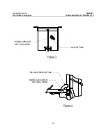
Страница 19: ...General Dynamics 4096 387 SATCOM Technologies 1 2M Ku BAND Rx Tx SERIES 1123 18 Canister Plate MARK AZIMUTH SETTING HERE Figure 3 Figure 4 Elevation Marking Plate MARK ELEVATION SETTING HERE...

Страница 20: ...ditions Should any damage be detected to a portion of the reflector contact the Customer Service Department at General Dynamics for recommendations involving reflector repair 5 2 MOUNT AND REFLECTOR S...

Отзывы: