Generac Power Systems PWRcell XVT076A03 Скачать руководство пользователя страница 5

Safety Rules & General Information

Installation Manual for Generac PWRCell Inverter

1

Section 1: Safety


Rules & General Information

Introduction

Thank you for purchasing a Generac PWRcell™ product.

The  Generac  PWRcell  inverter  is  a  storage-ready

inverter  that  connects  to  the  PV  Link™  optimizers  and

PWRcell batteries to form the Generac PWRcell system.
This  manual  provides  instructions  for  installing  the

PWRcell inverter, including mounting, wiring, and battery

integration information. The companion document to this

installation  manual  is  the  Generac  PWRcell  Inverter

Owner’s  Manual. See the owner’s  manual for complete

information  on  programming  and  configuring  the

PWRcell inverter. 
The  information  in  this  manual  is  accurate  based  on

products  produced  at  the  time  of  publication.  The

manufacturer  reserves  the  right  to  make  technical

updates, corrections,  and product  revisions at  any time

without notice.

Read This Manual Thoroughly

If any section of this manual is not understood, contact

the  nearest  Independent  Authorized  Service  Dealer

(IASD) or Generac Customer Service at 1-888-436-3722

(1-888-GENERAC), or visit 

www.generac.com

 for assis

-

tance. The owner is responsible for correct maintenance

and safe use of the unit.
This  manual must be used  in conjunction with all other

supporting  product  documentation  supplied  with  the

product.
SAVE THESE INSTRUCTIONS for future reference. This

manual contains important instructions that must be fol

-

lowed during placement, operation, and maintenance of

the unit and its components. Always supply this manual

to any individual that will use this unit, and instruct them

on  how  to  correctly  start,  operate,  and  stop  the  unit  in

case of emergency.

Safety Rules

The  manufacturer  cannot  anticipate  every  possible  cir

-

cumstance that might involve a hazard. The alerts in this

manual, and on tags and decals affixed to the unit, are

not all  inclusive.  If using  a procedure,  work  method,  or

operating technique that the manufacturer does not spe

-

cifically recommend, verify that it is safe for others and

does not render the equipment unsafe.

Throughout  this  publication,  and  on  tags  and  decals

affixed to the unit, DANGER, WARNING, CAUTION, and

NOTE  blocks  are  used  to  alert  personnel  to  special

instructions  about  a  particular  operation  that  may  be

hazardous if performed incorrectly or carelessly. Observe

them carefully. Alert definitions are as follows:

NOTE: 

Notes contain additional information important to

a procedure and will be found within the regular text of

this manual.
These  safety  alerts  cannot  eliminate  the  hazards  that

they indicate. Common sense and strict compliance with

the  special  instructions  while  performing  the  action  or

service are essential to preventing accidents.

How to Obtain Service

For assistance, contact the nearest Independent Autho

-

rized Service Dealer (IASD) or Generac Customer Ser

-

vice  at  1-888-436-3722  (1-888-GENERAC),  or  visit

www.generac.com

When contacting an IASD or Generac Customer Service,

always supply the complete model and serial number of

the unit as  given  on  its  data  decal  located on the  unit.

Record the model and serial numbers in the spaces pro

-

vided on the front cover of this manual.

(000100a)

Consult Manual. Read and understand manual
completely before using product. Failure to 
completely understand manual and product 
could result in death or serious injury.

WARNING

(000001)

DANGER

Indicates a hazardous situation which, if not avoided, 
will result in death or serious injury.

(000002)

WARNING

Indicates a hazardous situation which, if not avoided,
could result in death or serious injury.

(000003)

CAUTION

Indicates a hazardous situation which, if not avoided,
could result in minor or moderate injury.

Содержание PWRcell XVT076A03

Страница 1: ...of life This product is not intended to be used in a critical life support application Failure to adhere to this warning could result in death or serious injury Register your Generac product at https pwrfleet generac com 1 888 GENERAC 888 436 3722 Para español visita http www generac com service support product support lookup Pour le français visiter http www generac com service support product su...

Страница 2: ...this page See Serial Number Location When contacting an Independent Authorized Service Dealer IASD or Generac Customer Service always supply the complete model number and serial number of the unit Table 1 PWRcell Inverter Important Information Unit Model Number Unit Serial Number Date Purchased Commissioning Date 000393a WARNING CANCER AND REPRODUCTIVE HARM www P65Warnings ca gov ...

Страница 3: ... Accessing Wiring Compartment 14 Knockout Dimensions and Locations 14 Wiring Guidelines 15 Grounding Bar Wiring 16 DC Wiring 17 AC Wiring 17 Protected Load 18 Current Transformers CTs 20 Other Accessories 24 Section 6 Commissioning and Setup System Configuration 25 General Information 25 Commissioning the System 25 Registration 25 Connecting PWRcell Inverter to AC Power 26 Selecting Inverter Syste...

Страница 4: ...iv Owner s Manual for Generac PWRcell Inverter This page intentionally left blank ...

Страница 5: ...ry possible cir cumstance that might involve a hazard The alerts in this manual and on tags and decals affixed to the unit are not all inclusive If using a procedure work method or operating technique that the manufacturer does not spe cifically recommend verify that it is safe for others and does not render the equipment unsafe Throughout this publication and on tags and decals affixed to the uni...

Страница 6: ... 000187 WARNING Electrocution Potentially lethal voltages are generated by this equipment Render the equipment safe before attempting repairs or maintenance Failure to do so could result in death or serious injury Risk of injury Do not operate or service this machine if not fully alert Fatigue can impair the ability to operate or service this equipment and could result in death or serious injury 0...

Страница 7: ... damage DANGER 000145 DANGER Electrocution In the event of electrical accident immediately shut power OFF Use non conductive implements to free victim from live conductor Apply first aid and get medical help Failure to do so will result in death or serious injury 000599 Electrocution Turn battery disconnect OFF and de energize REbus before touching terminals Failure to do so will result in death s...

Страница 8: ...Safety Rules General Information 4 Installation Manual for Generac PWRCell Inverter This page intentionally left blank ...

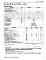
Страница 9: ...0 Output power factor rating AC 1 Operating voltage range AC XVT076A03 L N V rms 108 120 130 Operating voltage range AC XVT076A03 L L V rms 216 240 260 Operating voltage range AC XVT114G03 L N V rms 108 120 130 Operating output voltage range AC XVT114G03 L L V rms 184 208 228 Continuous output current AC grid tied A rms 32 PCS controlled current grid tied A rms 32 Continuous output current AC isla...

Страница 10: ...inverters disconnect from the grid and provide AC power to support protected loads when configured to do so This capability is referred to as islanding All PWRcell products use the REbus 380 VDC nanogrid to connect to each other The REbus nanogrid automates the flow of power to enable plug and play setup and operation of PWRcell equipment For more information about REbus visit www generac com In F...

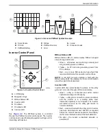
Страница 11: ... specific fault detected Inverter LED Inverter LED D communicates the status of the utility grid and or inverter through LED color and state Green utility is connected and within normal operational voltage and frequency Yellow utility grid is not within normal conditions and the inverter is in a waiting state User intervention typically is not required The inverter will restart as soon as the util...

Страница 12: ...still be energized unless the building AC disconnect or main service breaker is shut off To enter shutdown press and hold shutdown button E In shutdown mode PWRcell inverter will stop sourcing power to REbus and immediately disable all communicating power sources on REbus by sending a system wide system mode change signal NOTE Successful signal transmission relies upon proper configuration of PLM ...

Страница 13: ... units connected to that disconnect NOTE If an additional DC disconnect is added ensure the disconnect switch is DC rated for a minimum of 30 amperes 450 volts To initiate the PVRSS Open the inverter lid Locate the four DC disconnects to the left of the Generac Power Core Turn all disconnects with connected PV sources to the off position PV Links will open all SnapRS devices within 30 seconds cont...

Страница 14: ...itions result in a 300 second restart delay time after the trip threshold has been exceeded for the listed number of cycles Frequency Trip Thresholds See Table 3 2 for the default fixed frequency trip set points All over frequency and under frequency trip condi tions result in a 300 second restart delay time after the trip threshold has been exceeded for the listed number of cycles Value of 999 in...

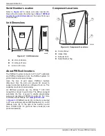
Страница 15: ...ces Figure 4 1 PWRcell Inverter Dimensions and Mounting Clearances Mounting Bracket Dimensions Figure 4 2 Mounting Bracket Dimensions 4 in 10 16 cm 28 in 71 15 cm 8 in 20 32 cm 28 1 2 in 72 4 cm 36 in 91 44 cm 8 in 20 32 cm 19 1 4 in 48 9 cm 8 1 2 in 21 6 cm 20 in 50 8 cm 8 in 20 32 cm 24 1 2 in 62 23 cm 010508 16 in 40 64 cm 1 1 2 in 3 81 cm 2 3 8 in 6 03 cm 009990 ...

Страница 16: ...he wall Fasteners must be suitable for the mounting surface Fasteners must engage at least two studs or other structural members Mounting bracket has clearance holes for 1 4 in fasteners with slots to accommodate different stud spacings 3 See Figure 4 3 Insert mounting bracket tabs A into inverter body slot B NOTE Figure 4 3 is for illustration purposes only Figure 4 3 Mounting Inverter onto Brack...

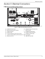
Страница 17: ...connects H Authorized Generac Personnel Only B REbus Bi directional DC Terminals I STOP Terminals C Internet Connection J Protected Loads Disconnect D DC Main Fuses K AC Grid Connection Terminals E Current Transformers CTs Accessory Ports L Protected Loads Terminals F Automatic Transfer Switches ATS Accessory Port M Grounding Bar G REbus Beacon Port N RGM PWR Gen Inhibit B C D M L K J I H G F E A ...

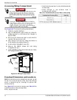
Страница 18: ... is intended only for mounting an optional LTE modem antenna See Figure 5 3 for knockout locations and Table 5 3 for available knockout sizes and quantities When using knockouts Install reducing washers to accommodate smaller conduit sizes Install rain tight or wet locations hubs in compliance with UL514B 000600 DANGER Electrocution Initiate a system wide shutdown and turn the PWRcell DC Disconnec...

Страница 19: ...ls as specified in Table 5 4 42 mm 1 21 32 in 50 mm 1 31 32 in 137 mm 5 13 32 in 97 mm 3 13 16 in 140 mm 5 17 32 in 2 13 16 in 72 mm 56 mm 2 7 32 in 40 mm 1 19 32 in 552 mm 21 23 32 in 50 mm 1 31 32 in 45 mm 1 3 4 in 55 mm 2 5 32 in 55 mm 2 5 32 in 26 mm 1 in 58 mm 2 9 32 in 62 mm 2 7 16 in 50 mm 1 31 32 in 48 mm 1 7 8 in 55 mm 2 5 32 in 55 mm 2 5 32 in 35 mm 1 3 8 in 10 mm 13 32 in 28 mm 1 3 32 i...

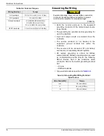
Страница 20: ...g wires are used as communications wires Ensure the following REbus devices have a low resistance wired connection back to the inverter grounding terminal bar PV Link PWRcell batteries Torque all terminals as specified in Table 5 5 Table 5 4 Terminal Torques Wiring Terminal Torque AC terminals 13 3 to 15 9 in lb 1 5 to 1 8 Nm DC terminals 12 in lb 1 35 Nm Ground terminals 4 to 6 AWG 45 in lb 5 Nm ...

Страница 21: ...Terminals 000686a DANGER Electrocution Never touch terminals when inverter and PWRcell DC disconnects are ON Doing so will result in death or serious injury 000646 Equipment damage Obey polarity markings when connecting REbus devices Reverse polarizing DC circuits could result in equipment or property damage WARNING 000645 WARNING Equipment damage Do not connect raw unregulated battery output to i...

Страница 22: ...bpanel Connect this subpanel to the protected loads terminals The protected loads output can provide on the order of 8 kW of continuous power See Specifications for exact values The inverter can surge up to 50 A for motor starting capabilities NOTE Actual power output for protected loads during a grid outage will depend on system sizing for batteries and solar array NOTE Backup power ratings are s...

Страница 23: ...e is expected in the future install a protected loads panel during inverter installation The protected loads panel will be fed by the grid while the system operates in Grid Tie mode Figure 5 6 Configuration for Adding Batteries Later A B C D E 009998 G A PV Array B PWRcell Inverter C Protected Loads Panel D Protected Loads Disconnect E AC Main Panel G Utility ...

Страница 24: ...ends using a hardwired connection to provide Internet connectivity Generac does not support using any wireless or power line carrier network devices Use these devices at your own discretion NOTE Ethernet cable run must be dedicated for the inverter This cable may not be daisy chained to another device including another PWRcell inverter Current Transformers CTs Current transformers CTs are required...

Страница 25: ...re multiple sets of CTs to fully measure the utility power being sent to the building For 4 wire 120 240 VAC split phase service Use two pairs of CTs to measure the service Use each pair of CTs to measure a pair of service conductors feeders within the main panel Use both RJ 45 jacks with two Cat 5 cables Connect CT1 from both cables to the same phase and CT2 cable from both cables to the second p...

Страница 26: ...ion may not be necessary or desirable To daisy chain a CT signal 1 Connect and calibrate a set of CTs to the first inverter See CT Calibration for more information 2 Run a new Cat 5 cable between the spare CT accessory port of the first inverter to either CT accessory port on the second inverter NOTE Running a new Cat 5 cable between inverter CT ports prior to calibration in Step 1 may cause calib...

Страница 27: ...T calibration Check wiring and CT integrity ct cal 5 0x8065 Line 1 3 don t have a valid CT calibration Check wiring and CT integrity ct cal 6 0x8066 Line 2 3 don t have a valid CT calibration Check wiring and CT integrity ct cal 7 0x8067 Line 1 2 3 don t have a valid CT calibration Check wiring and CT integrity ct cal 9 0x8069 Line 1 has multiple CTs on it or a CT is on the neutral wire Check wiri...

Страница 28: ...re When no LTE Modem is installed the power cable will be left unconnected and safely secured Complete installation instructions are included in the LTE Modem Kit Order part number PCLTE1 Technical Service Connection Service RJ 11 jack C is for use by authorized Generac personnel only Never connect any device to this jack without direct instructions from Generac Technical Service Figure 5 10 Acces...

Страница 29: ...nnected devices are turned ON Commissioning consists of seven steps 1 Register system 2 Energize the PWRcell inverter with AC power 3 Select Inverter system mode 4 Configure inverter settings 5 Select inverter compliance setting optional 6 Select ESS Grid Usage Mode optional 7 Enable REbus devices 8 Test islanding Registration NOTE If the system will not be connected to the Inter net installer wil...

Страница 30: ...See Figure 6 3 A list of system modes will be displayed with the current mode marked with an asterisk NOTE The list of modes may not include all those shown in Figure 6 3 Figure 6 3 Selecting System Modes 1 of 4 3 See Figure 6 4 Use the up and down arrows to highlight the desired mode and press the center button to select Figure 6 4 Selecting System Modes 2 of 4 4 Arrow right and press the center ...

Страница 31: ...12 1 Channel for REbus communications All devices in a system must use the same channel except REbus Beacon Do not set equipment to channel 0 unless performing Multiple Inverter System Commis sioning Procedure TargMaxImprtP 30 000 to 30 000 Watts 0 Maximum Threshold for importing power before the battery will dis charge in Self Supply Mode to offset TargMinImprtP 30 000 to 30 000 Watts 0 Minimum p...

Страница 32: ... loads as well as sup plying power to a utility when connected See Setting for Import Export Compliance for more information Export Limiting mode allows the user to restrict the export to a connected utility grid to a Export Limit value set by the installer When the Export Limit value is set to 0 this mode functions as like a Zero Export mode CRD200 Import Only compliance allowing the battery to b...

Страница 33: ...acon Configuring and Running a TOU Schedule 1 See Figure 6 11 Navigate to the Beacon device page and press the center button to enter the device menu Figure 6 11 Configuring TOU Schedule 1 of 4 2 See Figure 6 12 Use the up and down arrows to highlight Mod Settings and press the center button to enter the settings menu Figure 6 12 Configuring TOU Schedule 2 of 4 3 See Figure 6 13 Use the up and dow...

Страница 34: ...nd Figure 6 16 When enabled the LCD will alternate between a TOU Scheduler Running Screen and a Current System Mode screen Both screens will display the time until the next system change and the mode the system will change to The TOU Schedule name will be listed at the bottom of the device page Figure 6 15 Running Figure 6 16 Current System Mode See Figure 6 17 and Figure 6 18 On the home page the...

Страница 35: ...e device menu Figure 6 21 Disabling Beacon 1 of 3 2 Highlight Disable and press the center button 3 See Figure 6 22 Arrow sideways to Confirm and press the center button Figure 6 22 Disabling Beacon 2 of 3 4 See Figure 6 23 The status line on the Beacon device page will read Disabled NOTE The system will remain in the current system mode until the mode is changed manually or the sched uler is re e...

Страница 36: ...n 2 Navigate to the system home page and change the system mode to a backup only mode such as Pri ority Backup or Clean Backup See the Generac PWRcell Inverter Owner s Manual for more infor mation on system modes 3 Once the emergency has passed re enable the scheduler See Enabling Beacon TOU for more information NOTE If Priority Backup mode is not listed with the other system modes the system inst...

Страница 37: ...et Settings Figure 6 28 Ethernet Troubleshooting NOTE Ensure blue Cat 5 cable is reconnected to the Beacon after troubleshooting is complete On the Ethernet settings page the PWRview State should read Listen then a successful connection has not been made to the PWRview server If the inverter does not automatically connect to the network and begin communicating with the PWRview server perform the f...

Страница 38: ...eed to be restarted for the cross talked inverters 1 Close the AC backfeed breaker to supply AC power to one PWRcell Inverter AC Grid Input Out put Terminals This will allow the inverter to ener gize and illuminate the Inverter control panel 2 Perform Commissioning the System steps 1 7 3 Modify the PWRcell inverter PLM Channel to 0 NOTE PLM Channel 0 is a catchall channel Only use for inverters du...

Страница 39: ...r can be found on the front of the Beacon located inside the inverter as well as on the Beacon device page through the inverter s screen To find this number through the inverter s screen press the center button on the Beacon device page The RCP number will be displayed at the bottom of the menu screen 4 Type in the password labeled CODE for the REbus Beacon s Wi Fi network NOTE The code for the RE...

Страница 40: ...inverter software version in the Beacon Installer Tool select the Common sub menu option under the Inverter object as shown in Fig ure 6 31 Figure 6 31 Verifying Inverter Software The information populated upon selecting the Common sub menu option lists the manufacturer model version and serial number for the inverter The value displayed for Version contains the hardware version and software versi...

Страница 41: ...ettable Please be aware that once set certain Utilities may require the request to unset this setting come from the Utility To unset Zero Import please contact Generac PWRcell Technical Sup port Changing the value from DISABLED to ENABLED via the dropdown list will prevent the PWR cell batteries from importing power from the utility grid NOTE This feature is only available for inverter firmware ve...

Страница 42: ...the In compliance with line in the PDF If your utility requires proof of correct configuration save this PDF and send it to your utility It is recommend you keep a copy on file as well 1 To generate a proof of compliance PDF click on the Compliance PDF tab in the navigation menu 2 Click on Download Report 3 A new window will open in the browser with the report Verify information is correct and sav...

Страница 43: ...ects See PWRcell Inverter Wiring Compartment for location If a main fuse has blown determine the root cause of the issue before replacing it For assistance contact the nearest Independent Authorized Service Dealer IASD contact Generac PWRcell Technical Support at 1 855 635 5186 or call or Generac Customer Service at 1 888 436 3722 1 888 GENERAC or visit www generac com 000642 DANGER Electrocution ...

Страница 44: ...lder up and turn counterclockwise to release 8 Remove fuse from fuse holder and check for conti nuity using a multi meter 9 Insert replacement fuse into fuse holder 10 Reinstall fuse holder Turn clockwise until tight Figure 7 2 Removing Wiring Compartment Cover Recovery From an Error State Error events will force the PWRcell inverter into an error state where no DC power is exported though voltage...

Страница 45: ...er is in place between STOP terminals CTs will not calibrate Loose connection Check CT wiring Trigger manual CT calibration from the inverter device menu No REbus Beacon device page Beacon USB cable not connected Verify the USB cable is correctly connected to the Beacon and also to the Beacon accessory port in the inverter wiring compartment Inspect exposed sections of cable for damage Beacon wrap...

Страница 46: ...Troubleshooting 42 Installation Manual for Generac PWRCell Inverter This page intentionally left blank ...

Страница 47: ...This page intentionally left blank ...

Страница 48: ...rights reserved Specifications are subject to change without notice No reproduction allowed in any form without prior written consent from Generac Power Systems Inc Generac Power Systems Inc S45 W29290 Hwy 59 Waukesha WI 53189 1 888 GENERAC 1 888 436 3722 www generac com ...

Отзывы: