


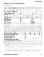


Electrical Connections
14
Installation Manual for Generac PWRCell Inverter
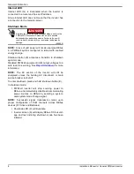
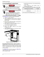
Accessing Wiring Compartment
. To access the wiring compartment:
1.
Initiate an inverter shutdown.
2.
Open all PWRcell DC disconnects (A). Verify DC
voltage reported on LCD screen has dropped to
below 10VDC.
3.
Disconnect AC Grid source from inverter. Wait for
Inverter LCD screen to turn off.
4.
Open inverter front cover by lifting the bottom to
horizontal (B) and pushing inward (C).
5.
Locate wiring compartment cover (D).
6.
Remove five M4X10 screws (E) and wiring
compartment cover.
7.
Verify all PWRcell DC and AC terminals are below
10V, using a multi-meter.
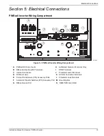
Figure 5-2. Wiring Compartment
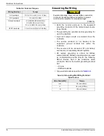
Knockout Dimensions and Locations
NOTE:
All knockouts are combination knockouts, except
for the 1/4 in trade knockout at the top of the left side
which is intended only for mounting an optional LTE
modem antenna.
See
for knockout locations and
for
available knockout sizes and quantities.
When using knockouts:
•
Install reducing washers to accommodate smaller
conduit sizes.
•
Install rain-tight or wet locations hubs in
compliance with UL514B.
(000600)
DANGER
Electrocution. Initiate a system-wide shutdown and turn the
PWRcell DC Disconnect Switch OFF on all connected
batteries before performing service. Failure to do so will
result in death, serious injury, or equipment and property
damage.
(000642)
DANGER
Electrocution. Verify all system voltages are safe before
wiring. Disconnect all AC and DC sources of power before
touching terminals. Failure to ensure no dangerous
voltages are present on conductors and terminals before
wiring will result in death or serious injury.
C
010238
B
E
D
A
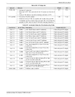
Table 5-3. Combination Knockout Size and Quantity
Combination Knockout Size
Quantity
3/4 in X 1 in
6
1/2 in X 3/4 in
7
0.575 in use only for LTE Modem Antenna
1


