


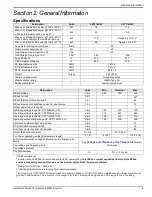


Location and Compliance
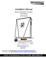
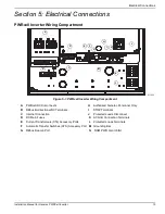
Installation Manual for Generac PWRcell Inverter
9
Section 3: Location and Compliance
Location
When installing the PWRcell inverter, consider the follow
-
ing:
•
The unit can be installed in indoor or outdoor loca
-
tions.
•
The inverter installation location must meet the
working space requirements in NEC Article 110.26.
Compliance
Follow all instructions included in this manual and use
appropriate practices for all product wiring and installa
-
tion.
Note on DC Wiring and the NEC
Some electricians or installers may be unfamiliar with DC
wiring in a residential setting. Note the following:
•
NEC 690.31 for DC PV circuits in buildings
•
NEC 215.12(C)(2) for correct DC wiring identifica
-
tion
Always adhere to applicable codes when marking and
installing DC conductors. See
. Mark or flag all conductors for
their polarity as appropriate.
•
It is recommended that REbus (+) conductors NOT
be green, white, gray, blue, or black.
•
It is recommended REbus (-) conductors NOT be
green, white, gray, or red.
Rapid Shutdown
The PWRcell Inverter is equipped with four DC discon
-
nects to initiate the Photovoltaic Rapid Shutdown System
(PVRSS). Each disconnect switch can be used to initiate
Rapid Shutdown in compliance with NEC 690.12 for all
PV Link and SnapRS units connected to that disconnect.
NOTE:
If an additional DC disconnect is added, ensure
the disconnect switch is DC rated for a minimum of 30
amperes, 450 volts.
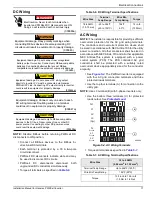
To initiate the PVRSS:
•
Open the inverter lid.
•
Locate the four DC disconnects to the left of the
Generac Power Core.
•
Turn all disconnects with connected PV sources to
the “off” position.
•
PV Links will open all SnapRS devices within 30
seconds controlling all PV conductors within the
array to less than 80V, and all conductors leaving
the array to below 30V.
NOTE:
Where the DC disconnect(s) in the inverter are
used as the Rapid Shutdown initiation device, proper
labeling is required for the exterior of the inverter lid to
indicate to first responders where to initiate Rapid Shut
-
down.
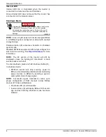
(000190)
DANGER
Loss of life. Property damage. Installation must
always comply with applicable codes, standards, laws
and regulations. Failure to do so will result in death
or serious injury.
WARNING
Electrocution. Refer to local codes and standards for
safety equipment required when working with a live
electrical system. Failure to use required safety
equipment could result in death or serious injury.
(000257)
(000182a)
WARNING
Equipment damage. Only qualified service personnel may
install, operate, and maintain this equipment. Failure to
follow proper installation requirements could result in death,
serious injury, and equipment or property damage.
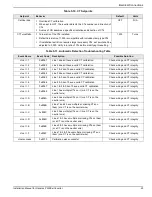
Table 3-1. REbus DC Wiring Coloring Convention
Wire
Color
REbus + (RE+)
Red
REbus - (RE-)
Black or Blue
Ground (GND)
Green


