ENC-3300-DTMF
Output Schematic
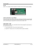
Connector for J3
The 9 pin connector is keyed to fit only one direction.
Example connection
This example shows a common wiring connection that can be used
for many different types of radios, although you must check your
radio for proper application. Numbers and colors in the table are for
instructional purposes and do not appear on the connector.
Genave/NRC,Inc. 9000-0000-086 rev 4
Pg. 12
J3 Pin
Purpose
1
Audio Output 1
2
Audio Output 2
3
Carrier Detect Input
4
Relay 7 - Common
5
Relay 7 – Normally Open
6
Relay 8 - Common
7
Relay 8 – Normally Closed
8
Relay 8 – Normally Open
9
Signal Common Ground
J3 Pin
Wire Color
Purpose
1
White
Audio output to transmitter
2
Yellow
Audio output to transmitter
3
Blue
Carrier detect from radio
8
Orange
Transmitter key-up / push-to-talk
9
Black
Common signal ground

