


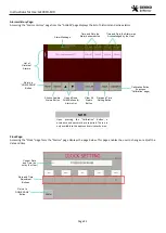
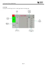

Instructions for Use: GEV019-100
Page 14
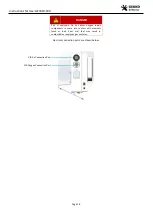
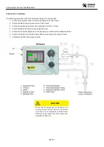
Internal Componentry:
The internal components of the GeVentor are shown below.
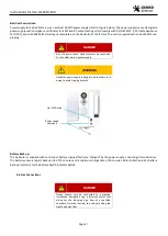
WARNING
It is not normal operation and use of the device to
have the GeVentor front cover opened. Only
qualified and authorised personnel are allowed to
open the front cover of the GeVentor.
1
SIS Gas (Air and Oxygen) Inlet Ports
9
Manifold
2
Oxygen Regulator
10
Main Pressure Relief Valve
3
Air Regulator
11
Programmable Logic Controller
4
GEV Regulator
12
GeVentor Expiration Valve (GEV)
5
Battery Charger Circuit Board
13
Expiratory Hose Connection Port (22 mm)
6
Vti Flow Control Valve
14 Pneumotachograph (for Vte)
7
Non-return Valves
15
Differential Pressure Sensor (Vti)
8
Pneumotachograph Tube Ports
16
Position for PEEP Valve
Pressure Relief:
Multiple pressure settings will prevent any overpressure event from occurring. Calibrated pressure sensors provide feedback to
the controller for cycle max pressure or alarm procedures. If Pmax pressure limits are achieved the first reaction is to close all gas
1
4
10
6
11
3
5
2
7
8
9
12
13
15
16
14


