


Critical Power
Modifications reserved
Page 8/25
GE_UPS_OPM_VHU_0K7_3K0_XUS_V011.docx
Operating Manual
VH700 UL, VH1000 UL, VH1500 UL, VH2000 UL & VH3000 UL
3.3
INSTALLATION PREPARATIONS
The UPS can be used in a stand-alone tower format using the two supporting stands (section 3.3.1), or can be mounted in
a 19 inch rack using the two mounting brackets (section 3.3.2). All required items are included in the delivery.
NOTE
Please consider the weight of the UPS. Lift the unit with the help of a second person.
3.3.1
Vertical installation – preparations
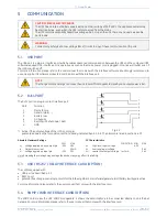
1.
Place the UPS horizontally on a table or desk.
2.
Assemble the four parts of the plastic supports (and metal
rails in case of VH Series 1500-3000 VA) at the bottom side
of the UPS cabinet, using the 4 screws provided.
*
The following two steps (3 and 4) must be performed by
qualified, skilled and service personnel only.
3.
*
Connect the DC connector of the internal batteries.
Battery block is 36V/72V and 7Ah/9Ah, as follows:
700VA
- 3 x 7Ah, 36 V
1kVA
- 3 x 9Ah, 36 V
1.5kVA
- 6 x 7Ah, 72 V
2kVA
- 6 x 9Ah, 72 V
3kVA
- 6 x 9Ah, 72 V
4.
*
Assemble the front panel: insert the two metal clamps at
the rear of the panel into the holes at the upper side of
the UPS, then click the front panel into position.
Fix the front panel with the screw provided.
5.
Place the UPS upright, and insert the two black plastic plugs
to cover the holes in the top panel of the UPS cabinet.
The VH Series UPS is now ready for further connections: proceed
with section 3.4.
Fig. 3.3.1: Installation preparations - Tower
2
1
3
4
5


