GE VH UL series Скачать руководство пользователя страница 13

Critical Power


Modifications reserved 

Page 13/25 

GE_UPS_OPM_VHU_0K7_3K0_XUS_V011.docx  

Operating Manual 

VH700 UL, VH1000 UL, VH1500 UL, VH2000 UL & VH3000 UL


3.6


CONNECTIONS 

3.6.1


Connecting interface devices 

.

If you do not want to use the communication capabilities of the UPS, please skip this section and proceed with 3.6.2. 

The UPS is equipped with two interface ports: a USB port and an RJ11 port, allowing advanced communication between 
the UPS and a computer (network). Refer to chapter 5 for more detailed information.  
 

3.6.2


Connecting power and load 


NOTE 

The UPS output sockets can be live as soon as the UPS is connected to the main power supply, even if 
the UPS has not been switched on via the front panel. 
The socket outlet shall be installed near the equipment and shall be easily accessible 


Switch off your computer, and unplug it from the socket-outlet. 


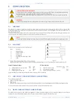
Fig. 3.6.2:  Connecting power and load


NOTE 

Grid supply is 120 Volt, 50/60 Hz,  
fused (see section 3.2) 


Disconnect the power cord from the computer (see note below) and 
connect this cord to the male input socket (1, fig. 3.4.b) at the rear of 
the UPS.  


VH3000 UL only

: connect the cable to the wall socket (1a, fig. 3.4.a).  


Add up the  power  consumption (in  VA) of  the  appliances  that  will  be 
protected by the UPS (‘the load’) and make sure that the resulting value 
does not exceed the VA output rating of the UPS. This way you ensure 
that the UPS is able to supply the required output and prevent that an 
overload situation will happen. 


4. 

Using  the  output  cords  (see  note  below)  connect  the  load  to  the 
appliance outlets (3 & 3a, fig. 3.4.a/b) of the unit. Spread the loads over 
the  appliance  outlets  as  equally  as  possible.  If  you  use  a  distribution 
box to connect more than one appliance per outlet, please note that 
the maximum AC-current ratings of each appliance outlets is 20A, and 
30A for the VH3000 UL (3 & 3a, fig. 3.4.a/b).  


Connect  the  mains  cord  of  the  UPS  to  a  working,  grounded  AC  wall 
socket outlet. The green LED ‘operation’ will blink now: mains power is 
available and the batteries are charging. If the LED does not blink but 
illuminates continuously instead, press keypad ‘0’ for one second.  


If  both  LEDs  ‘operation’  and  ‘alarm’  blink  and  the  beeper  sounds 
1/2secs,  phase  and  neutral  are  reversed  at  the  input  of  the  UPS. 
Please read 4.4.13 and take appropriate measures. 


For best results, allow the UPS to recharge the batteries during a period 
of approx. 2 hours. It is acceptable to use the UPS without first charging 
the battery, but the runtime may be reduced. 


NOTE: 

To connect UPS and loads use cables meeting the below requirements: 

Detachable UL Listed, SJT Type flexible cord with grounding type plug, maximum 14.76 ft. (4.5m) long. 
Cord type and ratings as per the table below:


UPS Model 

AC Power Cord 

UPS Outlet 

Rating (Minimum) 

Plug Type 

Connector Type 

VH700 UL 

VH1000 UL 

125V / 10A 

NEMA (L)5-15P or 

NEMA (L)5-20P 

IEC C13 

NEMA 5-20R 

VH1500 UL 

125V / 15A 

NEMA (L)5-15P or 

NEMA (L)5-20P 

IEC C19 

NEMA 5-20R 

VH2000 UL 

125V / 20A 

NEMA (L)5-20P 

IEC C19 

NEMA 5-20R and NEMA L5-20R 

VH3000 UL 

125V / 30A 

NEMA L5-30P 

NEMA 5-20R and NEMA L5-30R 


Содержание VH UL series

Страница 1: ...tical Power User Manual Uninterruptible Power Supply GE Consumer Industrial SA General Electric Company CH 6595 Riazzino Locarno Switzerland T 41 0 91 850 51 51 F 41 0 91 850 52 52 www gecriticalpower com ...

Страница 2: ...S_V011 Revision 1 1 Identification No SAP 1023054 Local 411254 Up dating Revision Concerns Date 1 0 Initial release 16 10 2012 1 1 Re branding ECN 2191 01 05 2015 General Electric Consumer Industrial SA All rights reserved The present publication and any other documentation supplied with the UPS system is not to be reproduced either in part or in its entirety without the prior written consent of G...

Страница 3: ...14 4 OPERATION 15 4 1 OPERATING PANEL 15 4 2 START UP 16 4 2 1 Start up mains available 16 4 2 2 Start up mains not available 16 4 3 USE NORMAL OPERATION 16 4 3 1 Normal operation conditions 16 4 3 2 No load shutdown 16 4 3 3 Output frequency 16 4 3 4 Switching off 16 4 4 USE STATUS AND ALARM INDICATIONS 17 4 4 1 Standby 18 4 4 2 Normal operation 18 4 4 3 eBoost operation 18 4 4 4 On bypass 18 4 4...

Страница 4: ...ndard NFPA75 While every care has been taken to ensure the completeness and accuracy of this manual GE accepts no responsibility or liability for any loss or damage resulting from the use of the information contained in this document This document shall not be copied nor reproduced without the permission of GE Due to technical improvements some of the information contained in this manual may be ch...

Страница 5: ...he weight of the UPS Lift the box with the help of a second person never try to lift it by yourself No liability can be accepted for any transport damage when the equipment is shipped in non original packaging Store the UPS in a dry location with the batteries in a fully charged state Storage temperature must be within 4 and 122 F 20 and 50 C If the unit is stored for a period exceeding 3 months o...

Страница 6: ...ric heaters toasters or vacuum cleaners into the UPS The UPS output is intended to be used only for electronic loads such as computers and telecommunications equipment The technical data as well as information concerning connecting requirements can be found on the rating label and in this document and shall be strictly observed 2 3 WARRANTY GE operating through its authorised agents warrants that ...

Страница 7: ...ated output power of the VH Series UPS refer to chapter 8 for the ratings The UPS is intended to be used in normal domestic and office situations The UPS must be powered from a single phase grounded socket outlet Do not use extension cords VH3000 This socket outlet shall be installed near the equipment and shall be easily accessible Place cables in such a way that no one can step on or trip over t...

Страница 8: ...s in case of VH Series 1500 3000 VA at the bottom side of the UPS cabinet using the 4 screws provided The following two steps 3 and 4 must be performed by qualified skilled and service personnel only 3 Connect the DC connector of the internal batteries Battery block is 36V 72V and 7Ah 9Ah as follows 700VA 3 x 7Ah 36 V 1kVA 3 x 9Ah 36 V 1 5kVA 6 x 7Ah 72 V 2kVA 6 x 9Ah 72 V 3kVA 6 x 9Ah 72 V 4 Asse...

Страница 9: ... came with the unit using the screws provided The following two steps 3 and 4 must be performed by qualified skilled and service personnel only 3 Connect the DC connector of the internal batteries 4 Assemble the front panel insert the two metal clamps at the rear of the panel into the holes at the right side of the UPS then click the front panel into position Fix the front panel with the screw pro...

Страница 10: ... Protects the UPS from damage caused by high input currents 2a Output thermal circuit breaker 3 Appliance outlets max rating 20A To connect the loads to the UPS Type NEMA 5 20R 700 VA 4 outlets 1000 3000 VA 6 outlets 3a Appliance outlet 2000 VA Type NEMA L5 20R max rating 20A 3000 VA Type NEMA L5 30R max rating 30A 4 DC connector not on VH700 UL To connect a battery extension pack for extended bat...

Страница 11: ...ing Manual VH700 UL VH1000 UL VH1500 UL VH2000 UL VH3000 UL Please refer to the previous page for more information Fig 3 4 b Rear panels VH2000 UL VH1500 UL VH1000 UL and VH700 UL Rack mount orientation 7 1 3 4 5 6 2 2000VA 1500VA 1000VA 700VA 8 7 1 3 4 5 6 2 8 7 3 4 5 6 2 1 3a 8 7 1 3 5 6 2 8 ...

Страница 12: ...k 36 Vdc or 72 Vdc should match 2 Make sure that the battery breaker on the rear side of the battery pack is in the OFF position 3 UPS and battery pack can be mounted together in one set of mounting supports for rack mount see 3 3 2 4 At the rear side the UPS and battery pack can be coupled using the coupling bracket that came with the battery pack 5 Connect the DC connector of the battery pack to...

Страница 13: ... prevent that an overload situation will happen 4 Using the output cords see note below connect the load to the appliance outlets 3 3a fig 3 4 a b of the unit Spread the loads over the appliance outlets as equally as possible If you use a distribution box to connect more than one appliance per outlet please note that the maximum AC current ratings of each appliance outlets is 20A and 30A for the V...

Страница 14: ... connector the switch should be of Normally Closed type for normal operation 3 Place the male connector to the connector on the rear panel of the UPS 8 fig 3 4 a b 4 When the switch is opened the UPS will shut down More information is given in section 4 4 14 WARNING The REPO Contact is a Safety Extra Low Voltage Circuit Connect it only to a SELV Circuit NOTE Use standard Low Voltage Cable in accor...

Страница 15: ...anneled directly to the load 5 LED on battery on in case of battery operation the mains power fails and the internal batteries supply the required power until either they are depleted or mains power returns 6 LED alarm blinks in case of an alarm 7 LED bar runtime capacity the remaining available battery runtime for the actual load in of the maximum runtime with the actual load 8 LED bar load indic...

Страница 16: ...e no load shutdown function is disabled The setting can be changed using the UPS monitoring software For more information please refer to the manual that came with the software If the no load shutdown function is activated and the load is smaller than the 5 threshold the 25 load LED will blink to warn you that the unit will switch off during a mains failure 4 3 3 Output frequency At power up defau...

Страница 17: ...2 o Normal operation 4 4 2 0 4 0 3 o eBoost operation 4 4 3 0 4 0 3 On bypass 4 4 4 0 4 0 4 hi o On battery 4 4 5 0 4 0 4 lo Battery low 4 4 6 25 0 4 hi Bypass out of limits 4 4 7 0 4 0 4 lo Overload 4 4 8 0 4 4 hi Battery bad 4 4 9 0 4 0 4 lo General alarm 4 4 10 0 4 0 4 lo hi o Shutdown pending 4 4 11 0 4 0 4 lo o No load shutdown enabled load 5 4 3 2 25 Input Phase Neutral reversed 4 4 13 hi RE...

Страница 18: ... provided that the bypass function was not disabled As the status of the UPS is unknown in this situation the indications on the operating panel may differ 4 4 5 On battery The UPS uses the energy stored in the batteries see section 8 Batteries runtime The runtime capacity LED bar will show the remaining runtime The UPS will shutdown after the batteries have been discharged automatic restart or if...

Страница 19: ...temperature Output out of tolerance 1 5 secs Charger failure Bypass out of limits see 4 4 7 Battery bad see 4 4 9 4 4 11 Shutdown pending The UPS monitoring software allows you to switch the UPS into standby mode after a programmable delay time During countdown the operation LED will blink 2x per second and the buzzer will beep every 5 seconds 4 4 12 Startup pending The UPS monitoring software all...

Страница 20: ...indicated by a blinking LED operation 2 Scroll through the four functions with keypad I one of the LEDs operation on bypass on battery or alarm will blink indicating which function has been selected see fig 4 5 3 Toggle the setting of the selected function by pressing switch O The LEDs on the LEDbar runtime capacity shows the setting 4 Store the new settings and leave the setup mode press keypad 0...

Страница 21: ...tteries have been partly discharged during transport storage or during the power failure Deep battery test A deep battery test to be initiated through the UPS monitoring software checks the actual battery capacity in order to ensure accurate runtime prediction During a deep battery test the batteries will be discharged NOTE When executing a deep battery test the available runtime in case of mains ...

Страница 22: ...bypass to standby and output power is lost 5 2 RJ11 PORT The RJ11 port is a plug in contact interface port Pin Function 1 Mains failure 2 General alarm 3 Battery low 4 On bypass 5 Remote UPS shutdown RxD 6 GND Active if the output voltage of the UPS is no longer Fig 5 2 guaranteed due to other circumstances than already indicated by pin 1 3 4 The alarms are listed in section 4 4 10 Absolute Maximu...

Страница 23: ...been designed to respect the environment using materials and components respecting eco design rules It does not contain CFCs Carbon Fluorine Chloride or HCFCs Halogen Carbon Fluorine Chloride The batteries contain lead which is a harmful substance for the environment Proper disposal or recycling of the batteries is required Refer to your local codes for disposal requirements Don t throw batteries ...

Страница 24: ...l not switch on without using battery start and the output has been off for a few secs see also 4 3 4 Line cord not connected Read 3 6 2 Connect line cord Dead wall socket outlet or mains voltage out of limits Contact qualified electrician Tripped Thermal Circuit Breaker See above LEDs operation and alarm blink buzzer sounds 1 2 secs UPS does not start P phase and N neutral are reversed at the UPS...

Страница 25: ...pical max 7º during tracking frequency range Typical transfer time msec 1 Overload capability fully protected against overload and short circuits Overload behaviour during battery operation 110 4 minutes 150 2 seconds Overload behavior during bypass operation depends on rating of thermal circuit breaker typical 125 of TCB value for 200 seconds 200 of TCB value for 10 seconds 300 of TCB value for 4...

Отзывы: