


Critical Power
Modifications reserved
Page 10/25
GE_UPS_OPM_VHU_0K7_3K0_XUS_V011.docx
Operating Manual
VH700 UL, VH1000 UL, VH1500 UL, VH2000 UL & VH3000 UL
3.4
REAR PANEL
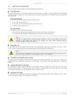
Figure 3.4.a shows a VH3000 UL. The differences with the rear panel - configuration of other models is
clearly indicated
in the text below.
1
Input socket – max. rating 20A
AC mains supply to the UPS
700-1000VA: IEC-C14
1500-2000VA: IEC-C20
1a Input plug – max. rating 30A
AC mains supply to the UPS
Type: NEMA L5-30P
2
Input thermal circuit breaker
Protects the UPS from damage caused by
high input currents
2a Output thermal circuit breaker
3
Appliance outlets - max. rating 20A
To connect the loads to the UPS.
Type: NEMA 5-20R
700 VA: 4 outlets
1000-3000 VA: 6 outlets
3a Appliance outlet
:
2000 VA:
Type: NEMA L5-20R / max. rating 20A
3000 VA:
Type: NEMA L5-30R / max. rating 30A
4
DC connector (not on VH700 UL)
To connect a battery extension pack for
extended battery runtime
5
Fan(s)
Electronically controlled cooling fan(s).
Make sure ventilation air can move freely
around and through the UPS.
6
USB port
See 5.1 for more information
7
RJ11 port
See 5.2 for more information
8
REPO (Remote Emergency Power OFF)
Fig. 3.4.a: Rear panel VH3000 UL - Tower
5
3
1a
2
7
6
3a
8
2a
4


