Contents
GFK-2721A
v
Introduction ................................................................................................................. 1-1
VersaMax PROFINET Scanner Overview ........................................................................ 1-2
VersaMax PROFINET Scanner Versions ......................................................................... 1-3
VersaMax PROFINET Scanner Specifications ................................................................. 1-4
VersaMax PROFINET Scanner Controls and Indicators ......................................... 1-5
VersaMax PROFINET Scanner LEDs ..................................................................... 1-5
Power Supply Modules ............................................................................................ 1-8
Ethernet Network Ports ............................................................................................ 1-9
USB Port ................................................................................................................ 1-11
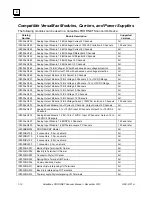
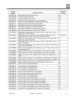
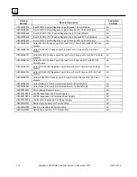
Compatible VersaMax Modules, Carriers, and Power Supplies ..................................... 1-12
Installation ................................................................................................................... 2-1
Module Installation ............................................................................................................ 2-2
Cable and Connector Clearance Requirements ...................................................... 2-3
General Installation Requirements ................................................................................... 2-4
Installation in Hazardous Areas ............................................................................... 2-4
ATEX Marking .......................................................................................................... 2-4
Installing the Module on a DIN Rail .......................................................................... 2-5
Removing the Module from the DIN Rail ................................................................. 2-5
Installing Power Supplies ......................................................................................... 2-7
PROFINET Scanner Power-up and Restart ..................................................................... 2-8
LED Operation .................................................................................................................. 2-9
Special LED Blink Patterns .................................................................................... 2-10
Firmware Updates........................................................................................................... 2-11
Firmware Update for Modules in the Remote Node .............................................. 2-11
Configuration .............................................................................................................. 3-1
Configuration Overview .................................................................................................... 3-2
Basic Configuration Steps ........................................................................................ 3-2
Configuration Tool .................................................................................................... 3-2
Adding a VersaMax PROFINET Scanner to a LAN .......................................................... 3-3
Configuring VersaMax PROFINET Scanner Parameters ........................................ 3-3
Adding VersaMax PROFINET Scanner Power Supplies ......................................... 3-5
Adding VersaMax Modules to a Remote Node ........................................................ 3-5
Adding Power Supplies between Modules ............................................................... 3-5
Configuring VersaMax Module Parameters ............................................................. 3-6
Configuring Analog Modules that Have Jumpers..................................................... 3-8
Assigning IO-Device Names ........................................................................................... 3-10
After the Configuration is Stored to the IO-Controller ..................................................... 3-10
Output Operation ............................................................................................................ 3-11
Clearing the IO-Controller Configuration ........................................................................ 3-11
Replacing PROFINET Scanner Hardware ..................................................................... 3-12


