GE Multilin
F35 Multiple Feeder Protection System
5-203
5 SETTINGS
5.7 CONTROL ELEMENTS
5
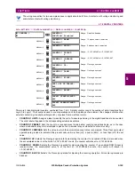
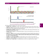
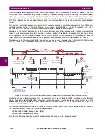
The broken conductor function should not be used to respond to fault transients and single-pole tripping/reclosing condi-
tions. Therefore, the time delay should be programmed to a sufficient length to ensure coordination with the breaker dead
time of the recloser function.
•
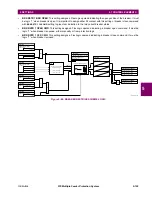
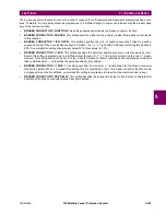
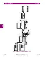
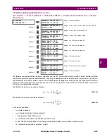
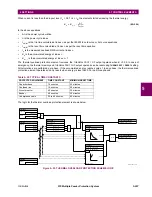
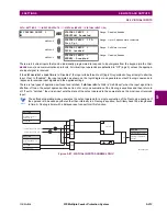
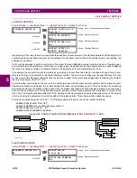
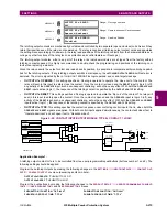
BROKEN CONDUCTOR 1 FUNCTION
: This setting enables and disables the broken conductor function.
•
BROKEN CONDUCTOR 1 SOURCE
: This setting selects a signal source used to provide three-phase current inputs
to this function.
•
BROKEN CONDUCTOR 1 I2/I1 RATIO
: This setting specifies the ratio of negative-sequence current to positive-
sequence current. When one phase conductor is broken, the I_2 / I_1 ratio with a balanced remaining two phases is
50%. So normally this setting should be set below 50% (for example, to 30%).
•
BROKEN CONDUCTOR 1 I1 MIN
: This setting specifies the minimum positive-sequence current supervision level.
Ensure this setting is programmed to a sufficient level to prevent I_2 / I_1 from erratic pickup due to a low I_1 signal.
However, this setting should not be set too high, since the broken conductor condition cannot be detected under light
load conditions when I_1 is less than the value specified by this setting.
•
BROKEN CONDUCTOR 1 I1 MAX
: This setting specifies the maximum I_1 level allowed for the broken conductor
function to operate. When I_1 exceeds this setting, this it is considered a fault. This broken conductor function should
not respond to any fault conditions, so normally this setting is programmed to less than the maximum load current.
•
BROKEN CONDUCTOR 1 PKP DELAY
: This setting specifies the pickup time delay for this function to operate after
assertion of the broken conductor pickup FlexLogic operand.
Содержание UR F35 Series
Страница 10: ...x F35 Multiple Feeder Protection System GE Multilin TABLE OF CONTENTS ...
Страница 30: ...1 20 F35 Multiple Feeder Protection System GE Multilin 1 5 USING THE RELAY 1 GETTING STARTED 1 ...
Страница 366: ...5 238 F35 Multiple Feeder Protection System GE Multilin 5 10 TESTING 5 SETTINGS 5 ...
Страница 396: ...6 30 F35 Multiple Feeder Protection System GE Multilin 6 5 PRODUCT INFORMATION 6 ACTUAL VALUES 6 ...
Страница 412: ...8 4 F35 Multiple Feeder Protection System GE Multilin 8 1 FAULT LOCATOR 8 THEORY OF OPERATION 8 ...
Страница 426: ...10 12 F35 Multiple Feeder Protection System GE Multilin 10 6 DISPOSAL 10 MAINTENANCE 10 ...
Страница 454: ...A 28 F35 Multiple Feeder Protection System GE Multilin A 1 PARAMETER LISTS APPENDIX A A ...
Страница 608: ...E 10 F35 Multiple Feeder Protection System GE Multilin E 1 IEC 60870 5 104 PROTOCOL APPENDIX E E ...
Страница 620: ...F 12 F35 Multiple Feeder Protection System GE Multilin F 2 DNP POINT LISTS APPENDIX F F ...
Страница 630: ...H 8 F35 Multiple Feeder Protection System GE Multilin H 3 WARRANTY APPENDIX H H ...
Страница 640: ...x F35 Multiple Feeder Protection System GE Multilin INDEX ...

