Page no. 16
CAD.fm
GE Healthcare
Senographe SecondLook Digital CAD System
Revision 1
Operator Manual 5189820-5-C-1EN
4-6 How are CAD overlays Displayed?
• Each image being viewed is displayed with its associated CAD overlay, if one exists. A
CAD label
at
the bottom of each image gives its status. Refer to the following sections for more information:
4-6-1
Image successfully analyzed
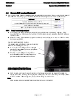
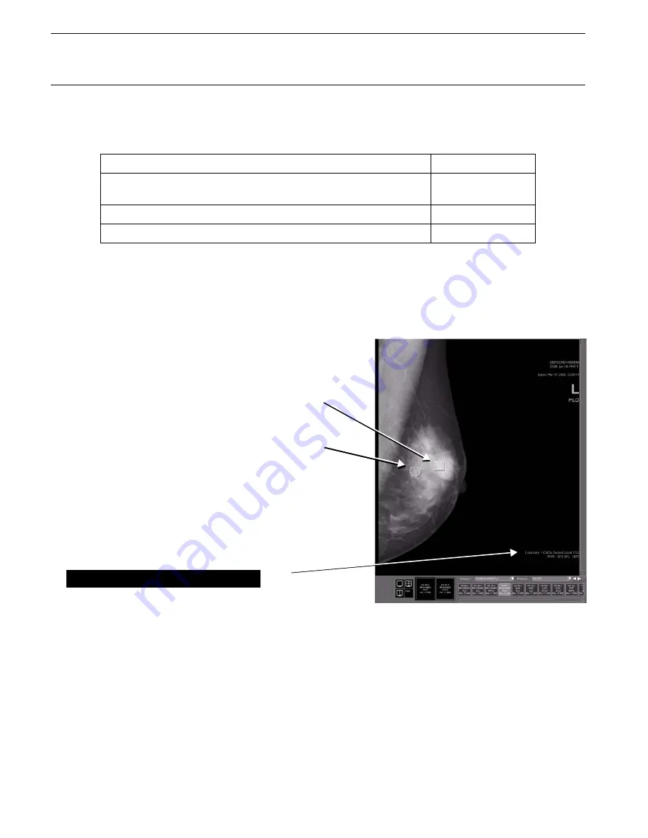
• If the image has been successfully analyzed, the CAD label is in the form
2 markers - iCAD
SecondLook V7.2.
It indicates the number of CAD markers present as well as the CAD software
version in use.
• When the SLDU identifies ROIs (regions of interest) on an image, the overlay includes a marker
to indicate each ROI:
• CAD markers are linked to specific points on the image and cannot be moved. Changing the
image orientation, zooming, drawing objects, adding text, etc. does not change the display of the
markers relative to the image; they move with the image as it is rotated.
Note:
CAD markers are automatically sized according to the size of the ROI.
CAD label
Refer to
2 markers - iCAD SecondLook V7.2
This indicates that the image has been successfully analyzed.
Section
CAD: Result not available
Section
CAD: This image can not be processed:
Section
SecondLook Digital CAD markers
The system uses two different markers to identify
ROIs for the radiologist's review:
• A rectangle surrounding a cluster of bright
spots, corresponding to a cluster of possible
microcalcifications.
• An ellipse surrounding a density with or
without radiating lines, corresponding to a
possible mass or architectural distortion.
CAD label with software identifier
2 markers - iCAD SecondLook V7.2:


