background image

Chapter 4: Troubleshooting

Service Mode

4-12

Service Manual

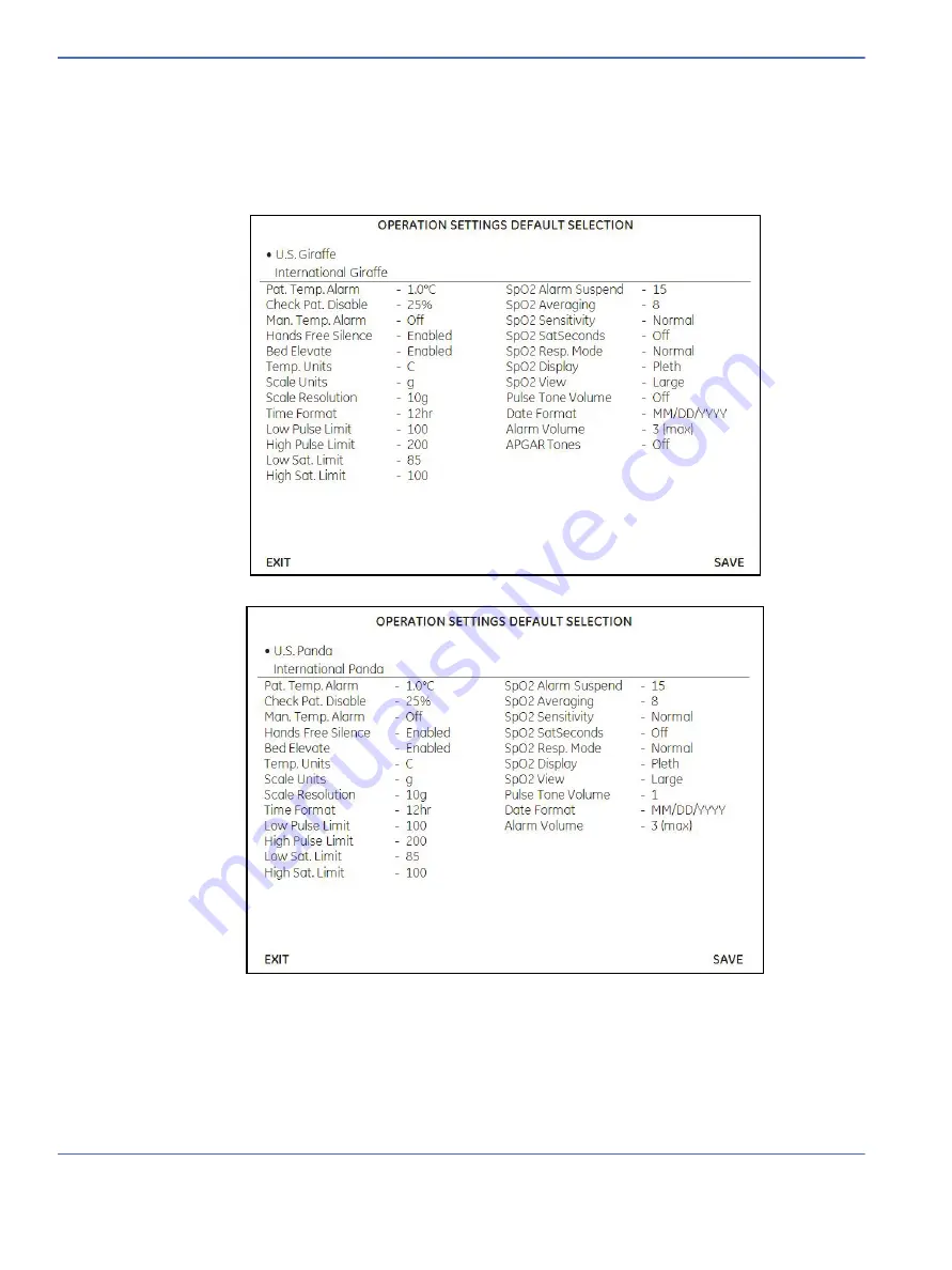
4.1.10 Set Defaults

To return Operation Settings to factory defaults, select US or International for the Giraffe or Panda unit you 
have, and press the Save key. Press the Back key to move the cursor back to the left side of the screen. Press 
the Back button again to update the display.

Note:

Language is not reset.

Содержание PANDA

Страница 1: ...Panda and Giraffe Warmers Service Manual M1128921 Revision J Class A 2007 2017 General Electric Company All rights reserved...

Страница 2: ...discontinue the product described at any time without notice or obligation Contact your GE Representative for the most current information Trademarks GE the GE Monogram Giraffe and Panda are trademar...

Страница 3: ...DA and new RoHS accessories D July 2013 Updated Masimo SET product names and Wall Mount Warmer installation instructions for fixed surfaces C May 2013 Updated enclosure dimension specifications and ad...

Страница 4: ...RH 2 Service Manual...

Страница 5: ...4 Probe Panel Assembly 1 8 1 2 5 Base Assembly Bedded and Freestanding Only 1 8 1 2 6 Bed Assembly Bedded Only 1 9 1 2 7 Optional In Bed Scale Bedded Only 1 9 1 2 8 Optional SpO2 Module 1 9 1 2 9 Gira...

Страница 6: ...ical Safety Tests 2 4 2 3 Mounting the Universal Adapter Plate 2 5 2 4 Scale Checkout Procedures 2 6 2 4 1 Visual Inspection 2 6 2 4 2 Center Weight Check 2 6 2 4 3 Off Center Weight Check 2 6 2 4 4 L...

Страница 7: ...racket Wall Mount Only 5 2 5 3 Heater Housing Repairs 5 2 5 3 1 Upper Heater Housing Removal 5 2 5 3 2 Heat Engine Assembly Removal Figure 5 1 and Figure 5 5 5 3 5 3 3 Heater Alignment Procedure 5 5 5...

Страница 8: ...Chapter 6 Illustrated Parts 6 1 6 1 Heater Housing 6 2 6 2 Electronics Enclosure 6 4 6 3 Probe Panel Housing 6 8 6 3 1 Probe Panel Housing with Masimo SET 1 SpO2 Jack 6 8 6 3 2 Probe Panel Housing wit...

Страница 9: ...ower Fail Recovery A 5 A 6 4 Masimo A 5 A 6 5 Masimo SpO2 Cables and Probes A 7 A 6 6 Power Fail Recovery A 7 Appendix B Electromagnetic Compatibility B 1 B 1 Electromagnetic Compatibility EMC Guidanc...

Страница 10: ...ts E 1 E 1 Pre Installation Preparation E 2 E 2 Wall Mount Bracket Installation E 3 E 3 Bumper Installation for Installations with Bassinets E 6 E 4 Heater Head Installation and Heater Alignment E 7 E...

Страница 11: ...not be used Parts that are broken missing plainly worn distorted or contaminated should be replaced immediately Should such repair or replacement become necessary GE Healthcare recommends that a telep...

Страница 12: ...ii Service Manual About this Manual User Responsibility...

Страница 13: ...lthcare deems said individual to be qualified to perform any such maintenance or repair service Moreover it should not be assumed that every acceptable test and safety procedure or method precaution t...

Страница 14: ...rmer Leaning against the side of the warmer may cause it to tip over Warning Bed to heater spacing less than approximately 85 cm will result in incorrect operation and may adversely affect the patient...

Страница 15: ...gh each step in every procedure before starting the procedure any exceptions may result in a failure to properly and safely complete the attempted procedure Caution U S Federal law restricts this devi...

Страница 16: ...z kazn k m pot ebuje n vod v jin m jazyce je zaji t n p ekladu do odpov daj c ho jazyka kolem z kazn ka Nesna te se o dr bu tohoto za zen ani byste si p e etli tento provozn n vod a pochopili jeho obs...

Страница 17: ...alia tarvittavan k nn ksen hankkiminen on asiakkaan vastuulla l yrit korjata laitteistoa ennen kuin olet varmasti lukenut ja ymm rt nyt t m n huoltoohjeen Mik li t t varoitusta ei noudateta seurauksen...

Страница 18: ...n peringatan ini dapat menyebabkan cedera pada pemberi layanan servis operator maupun pasien akibat sengatan listrik bahaya mekanik maupun bahaya lain IS A V RUN essi j nustuhandb k er a eins f anleg...

Страница 19: ...kalba Jei kliento paslaug tiek jas reikalauja vadovo kita kalba ne angl suteikti vertimo paslaugas privalo klientas Nem ginkite atlikti rangos technin s prie i ros jei neperskait te ar nesupratote io...

Страница 20: ...rv ncia deste aviso pode ocasionar ferimentos no t cnico operador ou paciente decorrentes de choques el tricos mec nicos ou outros PT PT ATEN O Este manual de assist ncia t cnica s se encontra dispon...

Страница 21: ...que no sea el ingl s el cliente deber encargarse de la traducci n del manual No se deber dar servicio t cnico al equipo sin haber consultado y comprendido este manual de servicio La no observancia del...

Страница 22: ...ik mekanik veya di er tehlikelerden dolay teknisyen operat r veya hastan n yaralanmas na yol a abilir KK VI C NH B O H ng d n s d ng d ch v n y ch s n d ng b ng ti ng Anh N u nh cung c p d ch v c a kh...

Страница 23: ...arth Terminal Alternating Current Alarm Silence European Union Representative Consult accompanying documents Catalog Number Serial Number UDI Unique Service Identifier The UDI is a unique marking for...

Страница 24: ...provided in the Operation and Maintenance Manual Standards This device is designed to meet the requirements of IEC 60601 2 21 with amendment IEC 60601 1 with amendment IEC 60601 1 2 with amendment UL...

Страница 25: ...erature baby mode control method Depending on the control method selected the heater is either regulated at the operator selected power level or the heater output is modulated to maintain the patient...

Страница 26: ...ize of the heater reflector and its compound elliptical shape designed specifically for this product the heater head is very compact compared with other warmers currently on the market This compact si...

Страница 27: ...Alarms may be silenced just as they would with the alarm silence button but without touching the unit The proximity sensor for the Hands Free Alarm Silence is located in the alarm light panel The ala...

Страница 28: ...ptional on Panda Standard on Giraffe All 3 Procedure light On Off switch All 4 Color display screen All 5 Resuscitation system optional Bedded and Freestanding 6 Bed with optional scale bed styles are...

Страница 29: ...dded and Freestanding 15 Brakes 2 for Freestanding 4 for Bedded Bedded and Freestanding 16 Elevating column optional Bedded 17 Tank guard on models with yoke equipped resuscitation systems Bedded and...

Страница 30: ...onnector All 24 Two accessory power outlets All 25 SpO2 system optional All 26 Removable rear bedside panel Bedded 27 Power cord inlet All 28 Mains power switch All 29 Suction Bottle holder only on un...

Страница 31: ...times 6 Baby temperature Can be displayed in degrees Celsius or degrees Fahrenheit The default setting is degrees Celsius 7 Alarm silence key Alarms can be silenced by pushing the key above the displa...

Страница 32: ...the rest of the product The warmer may be configured with either a bag and mask resuscitation system or a T piece resuscitation system 1 2 4 Probe Panel Assembly The probe panel assembly is located b...

Страница 33: ...h can weigh the patient The scale uses the graphics display on the warmer to display its measured weight 1 2 8 Optional SpO2 Module The SpO2 probe connects to the SpO2 module The SpO2 module uses an O...

Страница 34: ...Chapter 1 Functional Description System Functions 1 10 Service Manual 1 3 System Functions 1 3 1 System Overview Fully Loaded Bedded Shown FIGURE 1 4 System Overview...

Страница 35: ...tion Refer to Figure 1 6 The audio processor functions as the master watchdog processor and ensures the main application processor is responding normally If the audio processor detects abnormal functi...

Страница 36: ...ry Management A lithium ion rechargeable battery is located on the Control Board The audio processor provides charge control and monitoring of the battery Refer to Figure 1 7 The battery management in...

Страница 37: ...r provides power for the alarm The audio signal for a power fail alarm is a repeating sequence of 3 beeps from a piezoelectric buzzer on the Alarm Light Board The visual signal is one LED on the Alarm...

Страница 38: ...Chapter 1 Functional Description System Functions 1 14 Service Manual FIGURE 1 8 Power Failure...

Страница 39: ...the RS 232 port every 15 seconds 5 seconds The string will be formatted as follows Unit Type with version baby temperature set temperature current heater setting mode last recoded weight saturation p...

Страница 40: ...ered by the Control Board The Control Board includes a dedicated graphics controller with on board memory The LCD is backlit with two low voltage LED strings The LCD backlit driver is located on the C...

Страница 41: ...powered by mains power Refer to Figure 1 11 There are fuses for the mains power on the Power Board The power must be enabled by the elevating base relay on the Power Board This relay is under the con...

Страница 42: ...relay on the Power Board The mains power to the observation light is fused on the Power Board 1 3 12 Procedure Light Optional on Panda Warmer Mains power is converted to DC power by a dedicated 12V D...

Страница 43: ...efault heater power setting drops to 50 The display continues to flash Admit Baby until you press the Admit Baby key and start normal operation 1 3 13 2 Manual Mode assuming normal run state no alarms...

Страница 44: ...Chapter 1 Functional Description System Functions 1 20 Service Manual FIGURE 1 14 Manual Mode Heat Control...

Страница 45: ...desired skin temperature The system measures actual skin temperature via the patient probe The signal is an input to the Control Board converted to a digital signal read by the main application proce...

Страница 46: ...st the Temperature Simulator to 36 2 C Baby Temperature and wait for about 30 seconds You should see a decrease in the heat output 5 or 1 red bar every 30 seconds 9 Adjust the Temperature Simulator to...

Страница 47: ...The Pulse Oximetry SpO2 option utilizes an OEM module commonly used in other monitoring equipment For units that have the SpO2 option the SpO2 patient probe connects to the SpO2 module which is locate...

Страница 48: ...D Array located on the Alarm Light Board Refer to Figure 1 18 The LED array is controlled on and off by the alarm control signal provided by the main application processor or audio processor on the Co...

Страница 49: ...ter head housing the two parts of the housing along with the wire insulation form a double insulation system For the main bracket a sheet of insulating material is fitted between the bracket and the e...

Страница 50: ...Chapter 1 Functional Description System Functions 1 26 Service Manual 1 3 18 AC DC Power Distribution FIGURE 1 19 AC DC Power Distribution...

Страница 51: ...from the Panda and Giraffe products is repeated every two seconds The RS 232 parameters are 116000 bps baud rate no parity 8 data bits and one stop bit The data is in ASCII format the string is descr...

Страница 52: ...data output share the same female nine pin d type connector 1 4 3 3 Nurse Call Signals Pin 6 Closed contact under normal conditions that is power on no alarm recommended configuration Pin 1 Common con...

Страница 53: ...nspect suction tubing that is routed through the dovetail rail Replace the tubing as described in the cleaning instruction in the resuscitation operator supplement as required 2 1 2 Service Maintenanc...

Страница 54: ...ord for any signs of damage Replace the cord if damage is evident 3 Check that the cord retainer accessory outlet guard on the back of the control panel is in place 4 Examine the unit overall for any...

Страница 55: ...itch on the back of the unit and at the standby switch on the front control panel Verify the following The model type indicated on the screen matches the type of unit Panda or Giraffe bedded or non be...

Страница 56: ...istance check should be performed first Follow the operating instructions supplied by the manufacturer of the electrical safety analyzer to verify the following 2 2 3 1 Ground Resistance Check 1 Measu...

Страница 57: ...quired by local ordinances in single fault conditions in all possible operating modes the patient lead leakage current shall be less than 50 microamperes Note The isolation of the patient temperature...

Страница 58: ...C1 from SC2 The value must be 5000 10 2 4 3 Off Center Weight Check 1 Turn off the bed Clear all objects from the bed and ensure only the clear plate remains on the scale 2 Ensure the bed is level 3 T...

Страница 59: ...counts total 5 If the SC values change more than 5 counts 1 or both load cells might be defective Perform the following steps a Remove the scale top tray and the control board cover to access the load...

Страница 60: ...Chapter 2 Installation Maintenance and Checkout Scale Checkout Procedures 2 8 Service Manual...

Страница 61: ...2 Turn off the bed Ensure the bed is level 3 Enter service screen by turning on the bed while holding the Help and Alarm Silence keys until you hear 2 tones approximately 5 seconds 4 On the Main Menu...

Страница 62: ...Chapter 3 Calibration Scale Calibration Bedded Models Only 3 2 Service Manual...

Страница 63: ...sition of all 8 dip switch positions is OFF Note For versions of application software 1 0 9 and earlier refer to Appendix D for instructions about accessing and using service software 4 1 1 Unit Infor...

Страница 64: ...ion and Service Application Version of Heater Control Audio and Alarm Board Processors Version of Scale and SpO2 if present EPROM ID s for Control Power Alarm and SpO2 board if present Language Power...

Страница 65: ...nable Enable Bed elevate for Bedded Warmers with Fixed Adjustable Base Freestanding Warmers and Wall Mount Warmers Enable Disable Disengaged Disengaged Disengaged Temp units C C Only F C C Only Scale...

Страница 66: ...en appears as follows 4 1 5 Scale Calibration This menu displays the Scale Recalibration Count SR and Corrected value SC It also displays Scale software revision model resolution code and POST power o...

Страница 67: ...listed on the left of the screen The user changes the New Time settings by using the UP DOWN arrow keys and select button Once the desired settings are displayed in the New Time section they may be us...

Страница 68: ...This screen displays reference voltages readings from both patient probe thermistors one fixed thermistor input and the ambient temperature of the Control Board Expected Values ADC Channel Raw Value C...

Страница 69: ...test pattern and six selectable black and white test patterns The color test pattern should not have drop out or incorrectly displayed colors The 6 gray scale test patterns display alternate pixels t...

Страница 70: ...e key and help key It also provides a function to test the response of Hands Free Alarm Silence Note DIP Switch factory setting are all switches off 4 1 7 4 Alarm Diagnostics This provides the followi...

Страница 71: ...ter Readings This menu displays a resettable and non resettable hour meter power fail minutes as well as run hours versus output from 0 to 100 in 10 increments The resettable hour meter Power Fail cou...

Страница 72: ...s Date and Time Ambient Control Board temperature Event Name and Raw hexadecimal data More detail is displayed below the list for a selected event The user may scroll to any event in the list by using...

Страница 73: ...he View Hide symbol date time and sort preference using the UP DOWN arrow keys and Select key To return to cursor to the left side of the screen press the back key To return to the log display screen...

Страница 74: ...turn Operation Settings to factory defaults select US or International for the Giraffe or Panda unit you have and press the Save key Press the Back key to move the cursor back to the left side of the...

Страница 75: ...nd 26 Press the Stop key to stop the 25 Output Check 4 2 PC Command Line Interface Using a PC and null modem cable gives access to an additional diagnostic screen that allows you to update system soft...

Страница 76: ...p text version print service mode version info getbuttons print status of pushbuttons update update firmware logs retrieve stored logs pulsetone play single pulsetone set vol ncas print ncas input sta...

Страница 77: ...o audio processor heat heat control processor filesz size of the file to upload crc crc of the file to upload function Updates the specified processor with the file provided via xmodem upload After is...

Страница 78: ...tone vol 4 2 3 6 ncas Note NCAS is an early acronym for Hands Free Alarm Silence command ncas arguments none function Retrieves and displays the instantaneous state of the Hands Free Alarm Silence inp...

Страница 79: ...lable languages that can be used to set the desired language usage lang list set 4 2 3 10 lcd arguments state test to display lcd test pattern norm to return to normal display function Generates a mul...

Страница 80: ...information about the currently stored log data Note When prompted for a filename prior to xmodem file transfer please choose a descriptive filename denoting the unit serial number and timestamp e g H...

Страница 81: ...0187 12_31_08 13_45 logs Touchpanel Disabled Size of file to be transmitted 655872 Run local xmodem receive command now 7 At the Run local xmodem receive command now prompt do the following Click Tran...

Страница 82: ...with the following output xmodem error 69 Note It will take approximately 3 to 5 minutes to complete the download When complete the following output will appear xmodem transfer complete bytes transfer...

Страница 83: ...or attempted by anyone not having such qualifications Read completely through each step in every procedure before starting the procedure any exceptions may result in a failure to properly and safely...

Страница 84: ...tage OK remove upper housing and go to Step 27 If DC voltage not present continue 3 mm Hex T Wrench No mains power to 12V DC Power Supply 8 Turn off Standby Switch Remove rear panel on Electronic Encl...

Страница 85: ...ns voltage at power supply input connector pins 1 3 Disconnected faulty harness 24 If AC voltage not present turn OFF and check for open in harness Refer to 6 13 Wiring Diagrams If AC voltage OK conti...

Страница 86: ...place Alarm Light PCA Possible Causes Step Troubleshooting Procedure Comments Possible Causes Step Troubleshooting Procedure Comments Mains voltage too low 1 Using DMM measure AC voltage at accessory...

Страница 87: ...Power PCA 4 Disconnect transformer connector J24 5 Measure AC out across J24 pins 3 4 Dimmer switch OFF 0V Dimmer switch ON mains voltage 6 If test fails replace Power PCA Possible Causes Step Troubl...

Страница 88: ...nd bulb socket With new bulb installed check continuity through bulb should be 4 Ohms Bulb socket harness part 6600 1594 700 9 If continuity test fails replace bulb socket harness Bad harness connecti...

Страница 89: ...oting Procedure Comments Poor LCD cable connection 1 Check LCD cable connection at Control PCA J1 LCD Cable PN 6600 1412 600 2 If OK check the LCD cable connection at LCD module 3 If OK replace LCD mo...

Страница 90: ...between the Control PCA and Power PCA for correct pins Refer to section 6 13 Wiring Diagrams Power cable part 6600 1567 700 3 Check fuse F7 on Power PCA Needle nose pliers Ohm Meter 4 Check backlight...

Страница 91: ...agnose using the touch panel test 3 If unable to enter Service Mode via buttons refer to alternate method in section 4 4 4 2 below 4 Enter diagnostics button test 5 If the diagnostic test indicates ei...

Страница 92: ...e Causes Step Troubleshooting Procedure Comments Power PCA failure 1 Run heat engine health check in Service Mode Heater Connection failure 2 Check connections from the Control PCA to the Power PCA an...

Страница 93: ...Stat or Harness 2 Check T Stats or Harness by disconnecting J20 on the Power PCA Using Ohm Meter on the harness connector verify each T Stat is closed by measuring 1 Ohm across the two pins Refer to t...

Страница 94: ...ng Procedure Comments Heater Control Failure 1 Replace Power PCA Possible Causes Step Troubleshooting Procedure Comments Defective Disconnected cable 1 Check ribbon cable between Power and Control PCA...

Страница 95: ...g Procedure Comments Wrong mains voltage 1 If unit is plugged into the wrong mains voltage or mains voltage too high low then Power PCA will fail POST Power On Self Test Open or loose heater AC fuse c...

Страница 96: ...ontrol PCA s is properly seated If OK replace Control PCA 20 pin ribbon cable part 6600 1411 601 Possible Causes Step Troubleshooting Procedure Comments Defective Disconnected cable 1 Check ribbon cab...

Страница 97: ...anel switch connections to the Control PCA to make sure it is properly seated Defective battery 4 If light is still not lit check the battery voltage in Service Mode Replace battery if reading is 3V P...

Страница 98: ...ands free silence is enabled If it cannot be enabled check the Service Mode setting to make sure HFAS is enabled and save settings Open connection 5 Check ribbon cable from the Control PCA to the Alar...

Страница 99: ...2 Check if probe is seated properly If OK replace patient probe Defective rail harness 3 Remove upper housing and check Patient Probe Rail Harness connection at the Probe Panel Interface Board J54 Har...

Страница 100: ...patient probe connected and the 4 pin connector that mates to the Probe Panel Interface Board disconnected check continuity of harness by probing the 4 pin connector 6 Using Digital Multimeter verify...

Страница 101: ...jack plate is seated properly 3 If the blue SpO2 connector has been dislodged from the probe plate remove the bottom cover probe panel and snap the connector back into the connector plate 3 mm Hex Wre...

Страница 102: ...refer to section 6 9 Possible Causes Step Troubleshooting Procedure Comments Possible Causes Step Troubleshooting Procedure Comments Defective E Base 1 Plug spare line cord directly into E Base AC inl...

Страница 103: ...t connector If OK then is most likely a foot switch issue skip to section 4 4 10 2 Defective Power PCA 15 Check the voltage on Power PCA at test point 26 from 2 1 and verify that it is greater than 2V...

Страница 104: ...12V at pins 1 5 on the cable side 4 If there is still no DC skip to Step 8 Blown fuse on Power PCA 5 Using a DC Volt Meter check the voltage from chassis to the bottom side of fuses F7 12V and F8 3 5...

Страница 105: ...o test the front panel switch standby switch using an Ohm Meter at pins 1 2 Off Open On Short If Open there is no AC voltage to the Power PCA then the front panel switch is defective 13 If no power tr...

Страница 106: ...t controls the radiant heater Main Application Processor Microprocessor located on the Control PCA that provides system communication control and user interface Audio Processor Microcontroller on the...

Страница 107: ...only 6 round file bastard cut 6 mill file bastard cut Adjustable wrenches crescent Flashlight Stopwatch Tape measure Chip extractor tool Digital Multimeter DMM Safety Analyzer Static control workstat...

Страница 108: ...er the warmer bed to its lowest position 5 3 1 Upper Heater Housing Removal 1 For wall mount models remove the heater head from the wall bracket as instructed in 5 2 Heater Head Removal from Wall Brac...

Страница 109: ...en used recently the duct may be hot 2 If removing the heat engine disconnect the heater power connectors and ground wire Remove the 3 hairpin cotter pins located under each of the heater adjustment s...

Страница 110: ...at engine and exhaust duct are not shown for visibility Bottom mounting screw Main DC power supply Duct mounting screw 6 Power supply mounting plate Top mounting screw Duct mounting screw 5 Observatio...

Страница 111: ...and at 0 75 0 1 1 9 cm 0 25 cm distance from the center of the warmer unit Note Use a laser level with two wall leveling capability or a combination of T square and Plumb bob to locate the alignment s...

Страница 112: ...hapter 5 Repair Procedures Heater Housing Repairs 5 6 Service Manual FIGURE 5 2 Locating Alignment Spot for Freestanding Model FIGURE 5 3 Locating Alignment Spot for Wall Mount Model Used with Bassine...

Страница 113: ...Chapter 5 Repair Procedures Heater Housing Repairs Service Manual 5 7 FIGURE 5 4 Locating Alignment Spot for Wall Mount Model Used with a Fixed Surface...

Страница 114: ...tion 5 3 1 2 Remove the 2 captive screws that secure the electronic enclosure on either side of the lens Tilt the top of the Electronics Enclosure out to allow access to the screws securing the back o...

Страница 115: ...take it out of the housing 2 Disconnect the bulb electrical connector and slide the bulb from its spring retainer 3 After replacing the bulb confirm that the glass lens is properly aligned Electronic...

Страница 116: ...aptive screws 5 4 1 Power Board Figure 5 6 and Figure 5 7 1 For wall mount models remove the heater head from the wall bracket as instructed in section 5 2 2 Loosen the 2 captive screws at the top of...

Страница 117: ...ct model on the screen display only the first time that the unit is turned on after control board replacement See section 1 1 for information on warmer models 5 4 3 Lithium Ion Battery Replacement Fig...

Страница 118: ...e bottom edge of the enclosure while removing it from between the rails 9 Loosen the 4 captive screws that secure the power board panel and tilt it down away from the unit Pull out the Power Board Pan...

Страница 119: ...hex nut from the dimmer control and mounting bracket assembly 7 Disconnect the electrical connector from the power board and remove the dimmer control 5 4 6 Standby Switch Replacement Figure 5 8 1 Fo...

Страница 120: ...a 2 mm hex key to remove the 2 button head screws split ring washers and flat washers that secure it to the panel 7 Use a 10 mm wrench to remove the ground stud nut and star washer 8 The circuit break...

Страница 121: ...e new fuse is installed Do not pry them out use needle nose pliers and pull straight out Reinsert gingerly the same way Once damaged the socket can not be replaced in the field and a new Power Bd will...

Страница 122: ...Masimo SET 2 and Nellcor see Figure 5 11 5 5 2 1 SpO2 Interface Board Replacement for Masimo SET 1 Figure 5 10 1 Remove the bottom end cap from the West Dovetail Rail and remove the decorative strip...

Страница 123: ...n the kit 11 Connect SpO2 harness from east rail to SpO2 board assembly 12 Re install the loose harnesses under the tension clip Note Be sure to route the patient probe harness around the mounting bos...

Страница 124: ...be Panel plate making sure to properly align the flat portion of the connector with the D shaped hole 11 Remove the socket head screw which retains the tie wrap holding the three harnesses near where...

Страница 125: ...using Repairs Service Manual 5 19 5 5 6 Probe Panel Upper Housing Replacement 1 Follow procedures 5 5 1 through 5 5 4 as appropriate to remove all parts from the Probe Panel Upper Housing FIGURE 5 10...

Страница 126: ...nd wall mount models use a small screw driver to remove the rail end cap and then pull the strip downward out of the dovetail rail 2 For freestanding models insert a small screw driver into the back o...

Страница 127: ...ote This procedure requires two persons 1 If possible lower the elevating column to the lowest position and disconnect the base power cord from the back of the column Lock all the casters 2 Use a 4 mm...

Страница 128: ...e unit upright or carefully placed on its back 1 Lock all the other casters 2 Lift the caster off the floor and use blocks to support the leg near the caster you are replacing 3 Remove screw s from bo...

Страница 129: ...Unit Repairs Bedded and Freestanding Models Service Manual 5 23 FIGURE 5 14 Base Legs and Rails Freestanding Base Freestanding Rails Rail Mounting Blocks Foot switch Caster Dovetail rails Main bracket...

Страница 130: ...that are located on either side of the warmer about half way up the column It does not matter which side of the column either retaining screw can be removed If the unit is equipped with a suction cani...

Страница 131: ...l mounting block on each rail use a 4 mm hex key to remove the M8 set screw and the retaining plate and then use a 3 mm hex key to remove the four M4 screws attaching the mounting block to the rail wh...

Страница 132: ...two M8 set screws on each plate to 75 11 lb in 8 5 1 2 N m c Re install the base back onto the M10 bolts and use long forceps to re install the two M10 flat washers and then use a torque wrench to tor...

Страница 133: ...6 1 Chapter 6 Illustrated Parts This chapter illustrates the Giraffe and Panda Warmer service parts and includes the orderable service kit component part numbers...

Страница 134: ...ID 0 5 6600 0712 402 7 Screw M3 x 8 Btn Hd 6600 0706 405 8 Power Supply 12V 65W 2075961 001 9 Power Supply brkt 6600 2097 500 10 Alarm light lens 6600 2043 500 11 Spit ring washer M3 6600 0713 402 12...

Страница 135: ...ble clip M1085398 15 Nut M4 X 0 7 6600 0711 407 16 Push on clip grill retainer M1079756 17 Protective grill order 12 pcs item 16 6600 2032 500 18 Observation light bulb replacement M1121134 19 Observa...

Страница 136: ...18 M1076053 4 Split ring washer M3 X 3 1ID 0 8 6600 0713 402 5 Line filter M1107967 6 Card guide 4 5 M1079766 7 Control board See Table 6 1 on page 6 5 Lithium ion battery M1121133 8 Probe panel inte...

Страница 137: ...switch has a metal shaft you will need to order all four items 12 13 22 and 23 TABLE 6 1 LED Illustrated Parts Matrix for the Electronics Enclosure Failed Part Required Replacement Part Number PCA Di...

Страница 138: ...ng washer M3 X 3 1ID 0 8 6600 0713 402 4 Screw M3 X 8 Btn Hd 6600 0706 405 5 Spacer stacking M1083992 6 Card guide 6 M1079769 7 Power brd panel M1109625 8 Power board 2080440 001 Fuse kit M1118329 9 H...

Страница 139: ...13 432 25 Outlet panel 6600 2154 500 26 Mains switch 230V 9A 6600 1014 601 Mains switch 115V 12A 6600 1014 602 27 Connector IEC320 C14 inlet snap in M1100425 28 Connector Outlet snap in 6600 0583 600...

Страница 140: ...ding and Wall Mount 6600 2129 500 4 Tension clip M1110360 5 Washer M3 X 3 2 ID 0 5 6600 0712 402 6 Split ring washer M3 X 3 1 ID 0 8 6600 0713 402 7 Screw M3 x 8 Btn Hd SpO2 ground 6600 0706 405 8 Sup...

Страница 141: ...4 500 3 Jack plate Scale Pat probe 6600 2127 500 4 Split ring washer M3 X 3 1 ID 0 8 6600 0713 402 5 Screw M3 x 8 Btn Hd SpO2 ground 6600 0706 405 6 Washer M4 x 4 3 ID 0 8 6600 0712 403 7 Split ring w...

Страница 142: ...asher Refer to Table 6 2 4 Screw M8 x 20 skt flange lock 6600 1295 400 5 Insulating sheet Refer to Table 6 2 6 Base shroud Refer to Table 6 2 7 Elevating Column Refer to Table 6 2 8 Base plate Refer t...

Страница 143: ...er IS NOT Displayed Variant 2 Part Number IS Displayed 2 Screw M10x45 btn hd M1074119 2 Screw M8x40 btn hd M1161801 3 Split ring washer M10 6600 0713 407 3 Split ring washer M8 6600 0713 406 5 Insulat...

Страница 144: ...und 6600 0713 432 14 Lug assy 6600 0868 800 15 Split ring washer M8 6600 0713 406 16 Cap nut M8 6600 1215 400 17 Back maneuvering handle 2063211 001 18 Decorative strip Plastic 6600 2053 500 Strip Woo...

Страница 145: ...dle 2075719 001 6 Pontoon Wood Inlay Natural Maple 6600 1665 504 Cherry Maple 6600 1665 503 Medium Oak 6600 1665 502 Natural Oak 6600 1665 501 7 Spring rear button release 6600 1291 400 8 E clip 375 X...

Страница 146: ...600 1663 500 11 Spring 66 OD x 1 5L 6600 1292 400 12 Damper release handle bracket 6600 1660 500 13 O ring M1072016 14 Tilt release handle 6600 2073 500 15 Screw M6 X 12 Btn Hd 6600 0706 427 16 Split...

Страница 147: ...spring 6600 1079 400 4 Rear bed side panel assy Giraffe 6600 1655 500 Rear bed side panel assy Panda 6600 2063 500 Rear bed side panel assy tube management Giraffe 6600 2146 500 Rear bed side panel as...

Страница 148: ...405 15 Drawer 2 75 Plastic 6600 2085 500 Drawer 2 75 wood NAT OAK 6600 1667 501 Drawer 2 75 wood MED OAK 6600 1667 502 Drawer 2 75 wood CHERRY MAPLE 6600 1667 503 Drawer 2 75 wood NAT MAPLE 6600 1667...

Страница 149: ...ingle Drawer and Storage Shelf 1 3 1 Drawer 8 Plastic 6600 2120 500 Drawer 8 wood NAT OAK 6600 2123 501 Drawer 8 wood MED OAK 6600 2123 502 Drawer 8 wood CHERRY MAPLE 6600 2123 503 Drawer 8 wood NAT M...

Страница 150: ...ndle 2063211 001 14 M8 Flange Lock Screw 6600 1295 400 15 M4x12 SKT HD CAP Screw 6600 0707 410 16 INT Tooth Lock Washer 6600 0713 432 17 Hose Retaining Clip 6600 0862 501 18 M8 Socket HD CAP Screw 660...

Страница 151: ...r Kit 2063179 001 5 Wall Mount WM Spacer 2063197 001 6 Wall Mount Rail EAST 2063204 001 7 Wall Mount Rail WEST 2063205 001 8 Wall Mount Appearance Strip 2063200 001 9 Wall Mount Filler Panel 2063199 0...

Страница 152: ...KIT Polish 2063184 016 FRU WM Warmer Bracket KIT Chinese 2063184 017 FRU WM Warmer Bracket KIT Norwegian 2063184 018 FRU WM Warmer Bracket KIT Czech 2063184 019 FRU WM Warmer Bracket KIT Estonian 206...

Страница 153: ...er 6600 1573 700 Harness Mains Power 6600 1574 700 Harness Scale Rail 6600 1586 700 Harness SpO2 Rail Bedded Model Only 6600 1587 700 Wire Harness Warmer Observation Light Switch 6600 1588 700 Harness...

Страница 154: ...Scale EU Gravity Zone 7 M1147692 Bedded Panda In bed Scale EU Gravity Zone 8 M1147693 Bedded Panda In bed Scale EU Gravity Zone 9 M1147694 Bedded Panda In bed Scale EU Gravity Zone 10 M1147695 Bedded...

Страница 155: ...rm 6600 0853 800 Giraffe Tubing Management Arm 6600 0837 800 Giraffe HFOV Side Panels M1092332 Giraffe Corner Tray front right SW rear left NW 6600 1793 500 Giraffe Corner Tray front left SW rear righ...

Страница 156: ...nese M1231867 Masimo SET 2 SPO2 Upgrade Kit with Control BD Spanish Italian M1231841 Nellcor Oximax SPO2 Upgrade Kit Spanish Italian M1231868 Masimo SET 2 SPO2 Upgrade Kit with Control BD Danish Swedi...

Страница 157: ...2 Upgrade Kit Danish Swedish Norwegian Finnish M1231827 Nellcor Oximax SPO2 Upgrade Kit Danish Swedish Norwegian Finnish M1231869 Masimo SET 2 SPO2 Upgrade Kit Russian Czech Polish Greek M1231828 Nell...

Страница 158: ...ty Zone 1 M1147670 Panda IN BED Scale EU Gravity Zone 2 M1147687 Panda IN BED Scale EU Gravity Zone 3 M1147688 Panda IN BED Scale EU Gravity Zone 4 M1147689 Panda IN BED Scale EU Gravity Zone 5 M11476...

Страница 159: ...1111366 STICKER LABEL SET BRANDING GIRAFFE WARMER M1137000 STICKER Din Rail Weight Limit 3kg 6 11 1 Labels on the Back of Giraffe Warmers or Panda iRes Warmers Part Number Description M1111331 STICKER...

Страница 160: ...l Set Bedded Models Part Number Description M1110855 STICKER LBL SET WARNING HEATER GIRAFFE WRM Heater Grille Accessory Warning Label Set M1110855 Choose appropriate language labels each language will...

Страница 161: ...RMER Includes all labels shown in Figure 6 17 except patent labels M1217648 LBL NELLCOR PATENT GP WRM M1217559 LBL PATENT MASIMO MX GP WARMER M1125258 LBL PATENT MASIMO GP WARMER 6 11 4 Control Panel...

Страница 162: ...1 81 30 cm 25 cm from the floor MAX 2A 115v 50 60 Hz MAX 1A 220 240v 50 60 Hz w Heater head warning label See table next page Rating label See table next page Accessory load label M1110852 Mattress he...

Страница 163: ...2063007 012 Freestanding label set Danish 2063007 013 Freestanding label set Finnish 2063007 014 Freestanding label set Turkish 2063007 015 Freestanding label set Polish 2063007 016 Freestanding labe...

Страница 164: ...the center of the warmer head See Figure E 7 A B C D MAX 2A 115v 50 60 Hz MAX 1A 220 240v 50 60 Hz w Accessory load label M1110852 Speaker bafling see table next page Heater head warning label See ne...

Страница 165: ...Mount label set Portugese 2063008 012 Wall Mount label set Danish 2063008 013 Wall Mount label set Finnish 2063008 014 Wall Mount label set Turkish 2063008 015 Wall Mount label set Polish 2063008 016...

Страница 166: ...HIGH BRK F2 F3 F5 F6 FUSE 2A 125V SMD fast acting socketed F7 F8 6 3A 250V TIME LAG F9 F10 FUSE Submini 2A F1 F4 F11 F12 Note Fuse kit M1118329 includes 3 15 A 250 V 10 pcs 2A 250 V 10 pcs 6 3A 250 V...

Страница 167: ...Service Manual 6 35 Self resetting over current protection PTCs for Scale and SpO2 FIGURE 6 19 Control Board 2080437 001 Dipswitches Non replaceable fuse for backlight invertor LED 3 ON Charging OFF N...

Страница 168: ...voltage 1 8V 3 2 5V 2 3 3V 0 2V 0V The following are derived from the 12V input voltage ISO5V 5 5 0V 4 3 3VSTBY 2 12V 5 5V ni 5 6 12 1 Control Board TP 1 2 TP Value 1 3 3V analog 2 Ground analog 3 2...

Страница 169: ...t Points Service Manual 6 37 6 12 2 Power Board TP Value 20 1 Ground DC 20 2 5V 20 3 12V 22 1 Ground DC 22 2 3 3V 22 3 12V 25 1 Ground AC side not connected to earth 25 7 5V ni TP 20 TP 29 TP 22 TP 21...

Страница 170: ...115VAC 6600 1561 701 230VAC 6600 1561 702 M1073604 Obs Lights Transformer Elevating Base Assy Back Panel M1126291 115 VAC 6600 1556 700 230 VAC 6600 1557 700 Single Ground Post M1126293 To From Contr...

Страница 171: ...17 18 19 20 1 2 3 4 5 6 7 8 9 10 11 12 13 14 15 16 1 2 3 4 5 6 7 8 9 10 11 12 13 14 15 16 17 18 19 20 21 22 1 2 3 4 5 6 7 8 9 10 1 2 3 4 5 6 7 8 9 10 11 12 13 14 15 1 2 3 4 5 6 7 8 9 10 11 12 13 14 1...

Страница 172: ...Chapter 6 Illustrated Parts Wiring Diagrams 6 40 Service Manual...

Страница 173: ...28 A 230V 50 60 Hz 1 A 230V 50 60 Hz 2 19 A 240V 50 60 Hz 1A 240V 50 60 Hz Temperature 18 to 30 C Humidity 5 to 75 Non condensing relative humidity Pressure 70 106 kPa Air Velocity up to 0 3 m s Stor...

Страница 174: ...age estimated life 3000 hours Elevating base duty cycle 15 Alarm Volume At 3m away from the device the alarm level is 60 dBA at the maximum setting 50 dBA at the minimum setting Life The warmer is des...

Страница 175: ...idth 64 cm Depth 119 cm Weight 100 kg Panda Mattress Size 66 x 48 x 2 cm Giraffe Mattress Size 65 x 48 x 4 cm Bed Capacity 14 kg Bed Tilt 12 degrees continuous tilt Accessories Storage drawer package...

Страница 176: ...itude 0 03 1 5 was validated using signals supplied by a patient simulator SpO2 and pulse rate values were varied across the monitoring range over a range of weak signal conditions and compared to the...

Страница 177: ...ne percent was added to the accuracies for neonatal infant sensors to account for accuracy variation due to properties of fetal hemoglobin The Masimo SpO2 parameter with sensors has been validated for...

Страница 178: ...x 2 simulator This variation equals plus or minus one standard deviation which encompasses 68 of the population A 6 4 2 Specifications Warmer Expected Service Life The product is designed to meet a li...

Страница 179: ...minutes a normal power on sequence will occur instead of a mains power failure recovery Masimo SET 1 Cables GE Part Number RD SET GE 05 PATIENT CABLE 1 5M 5 FT MASIMO RD 4084 RD SET GE 12 PATIENT CABL...

Страница 180: ...Appendix A Specifications SpO2 Specifications A 8 Service Manual...

Страница 181: ...quipment Warning This equipment system is intended for use by healthcare professionals only This equipment system may cause radio interference or may disrupt the operation of nearby equipment It may b...

Страница 182: ...upply line 1kV for input output line Mains power quality should be that of a typical commercial or hospital environment Surge IEC 61000 4 5 1kV differential Mode 2kV common mode line 1kV differential...

Страница 183: ...3 V m 26 MHz to 1 GHz 10 V m 26 MHz to 1 GHz 3V 3 V m 3 V m normal operation 10 V m no hazard Portable and mobile RF communications equipment should be used no closer to any part of the Giraffe Panda...

Страница 184: ...ications Equipment and the Warmer The Giraffe Panda Warmer is intended for use in an electromagnetic environment in which radiated RF disturbances are controlled The customer or the user of the Giraff...

Страница 185: ...se rate PR 100 floats with user adjustable limits Low Pulse Rate 3 min 1 Primary 3 Oxygen saturation SpO2 85 floats with useradjustable limits Low SpO2 3 min 1 Primary 4 Check baby Radiant power 100 f...

Страница 186: ...ual Temperature alarm set 11 Disconnected temperature probe No longer getting a reading from the temperature probe Confirm Probe Jack Connection 2 min 2 to 1 after 30 secs Primary Operational in Baby...

Страница 187: ...much ambient light Masimo or Nellcor board indicates too much ambient light Check SpO2 3 min 2 to 1 after 10 secs Primary Only available if SpO2 is running 19 Unrecognized SpO2 probe Unrecognized prob...

Страница 188: ...1 Low perfusion Masimo board indicates low perfusion Low Perfusion No silence No audio none Only active during alert condition 2 Low signal IQ Masimo board indicates low signal IQ Low Signal IQ No sil...

Страница 189: ...ation time settings and diagnostics Refer to Figure D 1 To exit the service mode power down the unit Note If the unit will not boot up the service mode can be accessed by setting control board dipswit...

Страница 190: ...5C 1 0C Off Touchless silence Enable Disable Enable Bed elevate for Bedded Warmers with Elevating Base Enable Disable Disengaged Enable Bed elevate for Bedded Warmers with Fixed Adjustable Base Frees...

Страница 191: ...on calibration and used by the software to calculate the displayed value E Audio Test The Audio Test Utility allows the user to invoke the Low Priority Alarm High Priority Alarm and Pulse Tone F Odome...

Страница 192: ...and press enter to see available commands Note The LOGS command will display 6 log types using the following parameters POW_UP BUT_PUSH ALARM SILENCE SYSFAIL STATE CF Note Typing LOGS will capture al...

Страница 193: ...ng silenced SYSFAIL Captured information about a system failure STATE Captured information about the general state of the system CFG Captured information about the configuration settings SPO2SET Captu...

Страница 194: ...es in section 4 4 5 STATE Bytes 0 3 The patient set point listed in hexadecimal byte swapped format Note No decimal place is present 6d 01 00 00 can be looked at as 0x0000016d which translates to 365...

Страница 195: ...ty 0x0 for Maximum 0x01 for Normal Byte 3 Low Pulse Rate Limit Setting Byte 4 High Pulse Rate Limit Setting Byte 5 Low Saturation Limit Setting Byte 6 High Saturation Limit Setting With Nellcor SpO2 i...

Страница 196: ...Appendix D Troubleshooting Service Mode Application Software 1 0 9 and Earlier D 8 Service Manual...

Страница 197: ...ethod they devise Note Mounting the wall mount bracket and the bumper on the wall is not the responsibility of GE Healthcare service personnel The hospital or the medical facility shall arrange for th...

Страница 198: ...each Wall Mount Warmer unit See Figure E 1 Verify that the studs and track are securely fastened together at 12 30 5 cm intervals and to both the floor and ceiling tracks with 10 sheet metal screws Wa...

Страница 199: ...that the four bracket holes be placed on the center of the wall tracks and the top edge of the wall mount bracket must be 60 8 0 1 154 4 0 25 cm from the floor for installations to be used with bassin...

Страница 200: ...and hold the ring so the metal channel rests flush behind the wall Slide the plastic cap along straps with the other hand until the flange of the cap is flush with the wall c Place your thumb between...

Страница 201: ...l longer screws will be required To properly mount the warmer at least 2 screw threads must be engaged Call out Description Orderable Service Part Number 1 Toggler anchor bolt 6600 0413 400 Replacemen...

Страница 202: ...er on the wall such that it is leveled horizontally and its center is aligned with the center of wall mount bracket and the bumper holes are 7 17 8 cm from the floor Note For bassinets with a bumper b...

Страница 203: ...and at 0 75 0 1 1 9 cm 0 25 cm distance from the center of the warmer unit For installations to be used with fixed surfaces the alignment spot shall be at 25 75 0 1 65 cm 0 25 cm distance from the wa...

Страница 204: ...Appendix E Installing Wall Mount Units Heater Head Installation and Heater Alignment E 8 Service Manual FIGURE E 5 Laser level or Plumb bob T square Used to Locate the Alignment Spot on the Floor...

Страница 205: ...ppendix E Installing Wall Mount Units Heater Head Installation and Heater Alignment Service Manual E 9 FIGURE E 6 Laser level or Plumb bob T square Used to Locate the Alignment Spot on a Fixed Surface...

Страница 206: ...l on the wall as shown in Figure E 7 Place the bottom bar of the label indicating the minimum height at 32 1 81 30 cm 25 cm from the floor and vertically center align the label with the center of the...

Страница 207: ...heat path to the bed see Figure E 10 and that the caregiver can have unobstructed access to the warmer control panel probe panel rails and the bed surface Do not operate the warmer unless the cabinet...

Страница 208: ...stalling Wall Mount Units Enclosure Dimensional Specification E 12 Service Manual The following dimensions apply when the warmer is NOT being operated FIGURE E 8 Minimum Dimensional Requirements for t...

Страница 209: ...Appendix E Installing Wall Mount Units Enclosure Dimensional Specification Service Manual E 13 FIGURE E 9 Dimensions of Wall Mount Warmer...

Страница 210: ...Appendix E Installing Wall Mount Units Enclosure Dimensional Specification E 14 Service Manual The following dimensions apply when the warmer is being operated FIGURE E 10 Radiant Heat Path...

Страница 211: ...ng warmer operation Actual dimensions are facility specific and therefore must be determined by the facility prior to warmer operation Note 2 For repairs the warmer needs to be removed from the wall b...

Страница 212: ...vice Agent GE Healthcare 3350 SW 148 Avenue Suite 301 Miramar Florida 33027 USA Tel 1 954 744 5600 GE Medical Systems Trade Development Shanghai Co Ltd Building 1 96 Yiwei Road Pilot Free Trade Zone S...

Отзывы: