Chapter 6: Illustrated Parts
Freestanding Model Parts
6-18
Service Manual
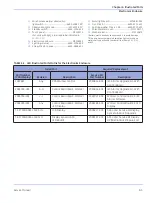
6.7 Freestanding Model Parts
FIGURE 6-15. Freestanding Model (Exploded View)
1.
FS Base*............................................................... 2063202-001
2.
FS Rail, West* .................................................... 2063201-001
3.
FS Rail, East*...................................................... 2063198-001
4.
FS Appearance Strip ...................................... 2063196-001
5.
FS Rail Mounting Block* ............................... 2063203-001
6.
FS Caster ............................................................. 2063285-001
7.
M10 Flat Washer ............................................. 2063283-001
8.
M10 Lock Nut .................................................... 2063281-001
9.
M10x80 Hex HD Screw*............................... 2063282-001
10.
M8x16 BTN HD Screw with Patch........6600-0706-435
11.
FS Probe Panel Housing Top ...................... 2063209-001
12.
M10 Push Nut*.................................................. 2062793-001
13.
FS North Handle............................................... 2063211-001
14.
M8 Flange Lock Screw ..............................6600-1295-400
15.
M4x12 SKT HD CAP Screw.......................6600-0707-410
16.
INT Tooth Lock Washer.............................6600-0713-432
17.
Hose Retaining Clip.................................... 6600-0862-501
18.
M8 Socket HD CAP Screw ....................... 6600-0707-428
19.
M8 Split Lock Washer ............................... 6600-0713-406
20.
M8 Flat Washer............................................ 6600-1284-400
21.
M4x25 Socket HD CAP Screw................ 6600-0707-448
22.
M4 Split Lock Washer ............................... 6600-0713-403
23.
M4 oversized Flat Washer ...................... 6600-0712-446
24.
Caster, Dual Lock ........................................ 6600-0890-400
25.
M8 Flat Washer............................................ 6600-0712-406
26.
M4 Flat Washer............................................ 6600-0712-403
27.
Retaining Plate..................................................2067984-001
28.
M8 Set Screw .....................................................2068114-001
*Order and use new M4 screws (6600-0707-448) when replacing
this part (See
3
14
15, 16
11
2
13
18, 19, 20
4
15, 22, 26
15, 16
17
4
21, 22, 23
28 27
24
8
7
1
6
9
5
12
10, 25
10, 25
Содержание PANDA
Страница 4: ...RH 2 Service Manual...
Страница 12: ...ii Service Manual About this Manual User Responsibility...
Страница 38: ...Chapter 1 Functional Description System Functions 1 14 Service Manual FIGURE 1 8 Power Failure...
Страница 44: ...Chapter 1 Functional Description System Functions 1 20 Service Manual FIGURE 1 14 Manual Mode Heat Control...
Страница 60: ...Chapter 2 Installation Maintenance and Checkout Scale Checkout Procedures 2 8 Service Manual...
Страница 62: ...Chapter 3 Calibration Scale Calibration Bedded Models Only 3 2 Service Manual...
Страница 172: ...Chapter 6 Illustrated Parts Wiring Diagrams 6 40 Service Manual...
Страница 180: ...Appendix A Specifications SpO2 Specifications A 8 Service Manual...
Страница 196: ...Appendix D Troubleshooting Service Mode Application Software 1 0 9 and Earlier D 8 Service Manual...


