background image

GEK-106426B

MIB High Impedance Bus Differntial Relay 

3-11

3 HARDWARE

3.4 HIGH-SPEED OVERCURRENT PROTECTION MODULE

3

3.4.5 OUTPUT CONTACTS CONFIGURATION

MIB relays provide one trip contact, one alarm (system ready) contact and four auxiliary contacts sharing one common
located in the high-speed overcurrent module. All output relays are form C relays.All output relays are form C relays. Only
one of the two states of the form C relay is connected to the output terminal. For each output relay it is possible to select
which state is preferred to have at the 


terminals, NC (normally closed) or NO (normally open).

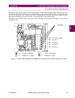
Next figure shows the PCB of a MIB


relay, and the location of the jumpers used to select the configuration of each output

contact (NO or NC).

Figure 3–11: PCB SCHEME SHOWING THE JUMPERS TO CONFIGURE THE OUTPUT CONTACTS (NC / NO)

Содержание Multilin MIB

Страница 1: ...E gemultilin ge com Internet www GEMultilin com Copyright 2006 GE Multilin MIB High Impedance Bus Differential Relay Instruction manual GEK 106426B GE Multilin Avda Pinoa 10 48170 Zamudio SPAIN T 34 9...

Страница 2: ...2 5 2 MINIMUM FAULT TO TRIP 87 2 9 2 6 MULTIPLE SETTING GROUPS 2 7 MEASUREMENT AND SELF TEST 2 7 1 MEASUREMENT 2 14 2 7 2 SELF TEST 2 14 2 8 USER INTERFACE 2 8 1 LED TARGETS 2 15 2 8 2 KEYPAD AND DIS...

Страница 3: ...3 4 2 3 PROPERTIES 4 4 4 2 4 GET INFO FROM RELAY 4 4 4 2 5 SEND INFO TO RELAY 4 4 4 2 6 PRINT SETUP 4 5 4 2 7 PRINT PREVIEW 4 5 4 2 8 PRINT 4 6 4 2 9 CLOSE 4 6 4 3 SETPOINT 4 3 1 SETTINGS 4 7 4 3 2 M...

Страница 4: ...4 7 4 OPERATIONS 7 4 1 ONE KEY OPERATION AND LAST TRIP DATA 7 6 7 4 2 HMI PASSWORD 7 6 8 RELAY COMMISSIONING 8 1 VISUAL INSPECTION 8 2 COMMENTS ON THE TEST EQUIPMENT 8 3 RELAY SETTING 8 4 WIRING AND...

Страница 5: ...TING SETTINGS A 4 1 FRAME STRUCTURE 10 9 A 4 2 SETTING CHANGE CONFIRMATION 10 10 A 4 3 EXAMPLE OF SETTING CHANGE 10 11 A 5 EVENTS A 5 1 FRAME STRUCTURE 10 14 A 6 OSCILLOGRAPHY A 7 ERRORS A 8 USED FORM...

Страница 6: ...ng chapter for information to help guide you through the initial installation procedures of your new relay CAUTION THE OPERATOR OF THIS INSTRUMENT IS ADVISED THAT IF THE EQUIPMENT IS USED IN A MANNER...

Страница 7: ...r physical damage Check the label at the side of the relay and check that the relay model is the same model ordered Figure 1 1 RELAY IDENTIFICATION LABEL MIB Ensure that the mounting screws have been...

Страница 8: ...ech euro ge com AMERICA ASIA AND AUSTRALIA GE MULTILIN 215 Anderson Avenue L6E 1B3 Markham ON CANADA Tel 1 905 294 6222 Fax 1 905 201 2098 E mail multilin tech ge com The information provided herein d...

Страница 9: ...N If you want to communicate with the relay using a computer through the front serial port please ensure that the computer is grounded to the same ground as the relay In case of using a portable compu...

Страница 10: ...the Install Now button and follow the installation instructions to install the no charge EnerVista software 3 When installation is complete start the EnerVista Launchpad application 4 Click the IED S...

Страница 11: ...is selected choose from the list the software program related to the specific model and click the Download Now button to obtain the installation program 7 When EnerVista detects that there is already...

Страница 12: ...different versions of set up program from the Web Figure 1 6 9 EnerVista Launchpad will obtain the installation program from the Web If the version you already have is the last one on the Web the fol...

Страница 13: ...lled in the directory indicated and the installation program will automatically create icons and add ENERVISTA MII SETUP to the Windows start menu 14 Follow the on screen instructions to install the E...

Страница 14: ...ogram group where the application will be added to is shown in the Selected Program Folder window Click Next to begin the installation process and all the necessary program files will be copied into t...

Страница 15: ...tial Relay GEK 106426B 1 2 ENERVISTA MII SETUP SOFTWARE 1 GETTING STARTED 1 18 Click Finish to end the installation The MII device will be added to the list of installed IEDs in the EnerVista Launchpa...

Страница 16: ...e relay s RS485 port from a computer s RS232 port a RS232 RS485 converter box is required GE Multilin offers F485 DAC300 and RS232 485 converters This converter box is connected to the computer using...

Страница 17: ...Differntial Relay GEK 106426B 1 3 MII RELAY FAMILY HARDWARE 1 GETTING STARTED 1 Figure 1 13 RELAY KEYPAD AND DISPLAY Using this keypad it is possible to access all the different menus in the relay and...

Страница 18: ...value for each phase Idiff1 Idiff2 Idiff3 Pressing the Menu button accesses the second level To access information within the same hierarchical level horizontal movement push the up down arrow button...

Страница 19: ...1 14 MIB High Impedance Bus Differntial Relay GEK 106426B 1 4 USING THE KEYPAD AND DISPLAY 1 GETTING STARTED 1...

Страница 20: ...on Units 87 1 and 87 2 CONTROL Reset 86 Close METERING Differential currents INPUTS OUTPUTS Programmable digital inputs and outputs Up to 3 Differential current inputs COMMUNICATIONS Front RS232 port...

Страница 21: ...ng the necessary settings and the resulting sensitivity to low current bus faults is very simple and straightforward requiring only knowledge of the CT secondary excitation characteristics and their s...

Страница 22: ...106426B MIB High Impedance Bus Differntial Relay 2 3 2 PRODUCT DESCRIPTION 2 2 INTRO 2 Figure 2 1 SINGLE LINE DIAGRAM BUS BAR APPLICATION MIB 30 Figure 2 2 SINGLE LINE DIAGRAM GENERATOR APPLICATION MI...

Страница 23: ...High Impedance Bus Differntial Relay GEK 106426B 2 2 INTRO 2 PRODUCT DESCRIPTION 2 Figure 2 3 SINGLE LINE DIAGRAM REACTANCE APPLICATION MIB 30 Figure 2 4 SINGLE LINE DIAGRAM ONE WINDING RGF APPLICATIO...

Страница 24: ...GEK 106426B MIB High Impedance Bus Differntial Relay 2 5 2 PRODUCT DESCRIPTION 2 2 INTRO 2 Figure 2 5 SINGLE LINE DIAGRAM TWO WINDING RGF APPLICATION MIB 20...

Страница 25: ...n the access is local by the RS232 port the back port is disabled and the relay will not serve any petition or command sent by the rear port When the access is local by keypad the back port is not dis...

Страница 26: ...eceive the differential currents corresponding to phase A B and C The elements will measure the three differential currents and operate if any of them surpass the pickup setting during the specified t...

Страница 27: ...margin factor RE stabilizing resistance 2000 Calculations need only be made with the maximum value of IF for single phase and three phase faults If the relay is applicable for these conditions it wil...

Страница 28: ...m internal fault current required for the particular 87 pickup setting Where IMIN Minimum internal fault current to trip 87 n Number of breakers connected to the bus i e number of CTs per phase I Seco...

Страница 29: ...s number is higher than 24 maximum number of events stored this means that only the last 24 will be stored This event record is stored in a capacitor backed up RAM memory Events functionality in MIB i...

Страница 30: ...f oscillo is a circular counter that increases with each generated oscillography This value appears on the relay status and is used only for informative purposes The oscillography record is stored in...

Страница 31: ...the protection functions 3 Oscillography trigger by communications 4 Oscillography trigger by digital input In the ADVANCED SETTINGS group there is a sub group called OSCILLOGRAPHY MASKS from where t...

Страница 32: ...active at a given time Users can select which setting group is active using a setting sending a command to the relay from the communications program or by a digital input Settings are divided in two d...

Страница 33: ...l values for differential currents Accuracy is 1 at nominal current and 3 in the complete range 2 7 2 SELF TEST Self monitoring tests are carried out both when the unit is started up and during normal...

Страница 34: ...10 and MIB 20 87 1 Trip Indicates that the trip has been issued by 87 1 87 2 Trip Indicates that the trip has been issued by 87 2 87 1 Pickup Indicates that element 87 1has picked up 87 2 Pickup Indic...

Страница 35: ...o 19200 bps Up to 32 MIB relays can be connected daisy chained on the same communication circuit Each relay must be assigned a different Modbus Address using a setting if multiple relays are connected...

Страница 36: ...ify the relay is provided in the following table ACCESSORIES A depth reducing collar can be ordered separately This collar reduces the mounting depth in 63 mm 2 48 inches MIB 0 C E 0 0 0 0 0 DESCRIPTI...

Страница 37: ...Delay Timing Accuracy Reset Type Fundamental 1 A 0 005 to 0 400 A in steps of 0 01 A 97 to 98 typical 3 in the complete range 1mA 15 ms at 4 x pickup 0 00 to 600 00 sec in steps of 0 01 s 3 of operat...

Страница 38: ...mption Max 10 W Proper backup time date time and log memory without power supply voltage 1 week 2 10 4 3 LOW RANGE HID MODULE Rated DC Voltage Min Max DC Voltage 48 Vdc 38 57 Vdc 2 10 4 4 HIGH RANGE H...

Страница 39: ...8 Vdc 16 A 48 A 2 6 A 125W 125 Vdc 16 A 48 A 0 6 A 75 W 250 Vdc 16 A 48 A 0 5 A 125 W AC Resistive 120 Vac 16 A 48 A 16 A 1920 VA 250 Vac 16 A 48 A 16 A 4000 VA AC Inductive PF 0 4 250 Vac 10 A 30 A 1...

Страница 40: ...MODULE SPECIFICATIONS ARE SUBJECT TO CHANGE WITHOUT NOTICE 2 11 1 VOLTAGE LIMITERS STABILIZING RESISTORS TECNOLOGY MOV METAL OXYDE VARISTOR Nominal Voltage VDC Nominal Voltage VAC Nominal Current DC P...

Страница 41: ...nominal voltage Pickup value 60 of nominal voltage OPERATING TIME at nominal voltage Close time N O contact 25 ms Open time N C contact 20 ms CONTACTS Continuous current 10 A continious 20 A during 1...

Страница 42: ...ctromagnetic fields with amplitude modulation ENV 50140 10 V m Radiated Electromagnetic fields with amplitude modulation Common mode ENV 50141 10 V m Radiated Electromagnetic fields with frequency mod...

Страница 43: ...2 24 MIB High Impedance Bus Differntial Relay GEK 106426B 2 11 TECHNICAL SPECIFICATIONS FOR HID MODULE 2 PRODUCT DESCRIPTION 2...

Страница 44: ...EW The MIB system incorporates electronic components that might be affected by electrostatic discharge currents flowing through certain component terminals The main source of electrostatic discharges...

Страница 45: ...stainless steel case The case contains a metallic panel to which the MOV Metal Oxide Varistors and the stabilizing resistors are hooked as well as the connections base for the latching relay and inte...

Страница 46: ...Differntial Relay 3 3 3 HARDWARE 3 2 HIGH IMPEDANCE MODULE DESCRIPTION 3 Wiring is made in the rear side of the module Drilling dimensions are shown on the drilling dimension diagram Figure 3 3 DIMEN...

Страница 47: ...ts high highly resistant to corrosion It is made of stainless steel AISI 304 coated with an epoxy layer and the rest of the metallic pieces are covered with a high quality resistive coating that has s...

Страница 48: ...IMPEDANCE MODULE DESCRIPTION 3 3 2 3 REAR DESCRIPTION The relay is wired through the terminal blocks located at the rear of the unit The maximum recommended cable section for this terminal board with...

Страница 49: ...K 106426B 3 3 WIRING 3 HARDWARE 3 3 3WIRING 3 3 1 TYPICAL WIRING DIAGRAM Recommended cable section 12 16 AWG Copper conductor only Tightening torque 1 2 Nm Figure 3 5 TYPICAL WIRING DIAGRAM FOR MIB RE...

Страница 50: ...WIRING 3 3 3 2 CONTROL POWER CAUTION CONTROL POWER SUPPLIED TO THE RELAY MUST MATCH THE RATED VOLTAGE OF THE RELAY IF THE VOLTAGE IS APPLIED TO THE WRONG TERMINALS DAMAGE MAY OCCUR Table 3 1 CONTROL P...

Страница 51: ...er of High Impedance Differential Elements is 1 the HID will have only one input If the Number of High Impedance Differential Elements is 2 the HID will have two inputs and If it is Bus machine applic...

Страница 52: ...ter through the front and with the relay mounted in the panel The modular design of the relay simplifies repair or replacement of its components without the need to manipulate the wiring These types o...

Страница 53: ...ted to the relay common negative terminal A10 The maximum external voltage source voltage for this arrangement is 300 Vdc The voltage threshold at which an input will detect a closed contact input dep...

Страница 54: ...All output relays are form C relays All output relays are form C relays Only one of the two states of the form C relay is connected to the output terminal For each output relay it is possible to selec...

Страница 55: ...groups In this case the number of outputs is reduced to three Jx jumper is closed in the factory default configuration It is possible to order relays with Jx removed The figure shows the factory defa...

Страница 56: ...tact combining OUT1 and OUT2 Group 2 Terminals B9 A7 OUT3 Standard output contact Terminals B10 A7 OUT4 Standard output contact 3 4 6 1 OUTPUT CONFIGURATION AT TERMINALS B8 B7 To have a normally open...

Страница 57: ...3 14 MIB High Impedance Bus Differntial Relay GEK 106426B 3 4 HIGH SPEED OVERCURRENT PROTECTION MODULE 3 HARDWARE 3 Figure 3 13 OUT2 AND OUT1 CONFIGUTATION TO ACT AS A NORMALLY OPEN CONTACT...

Страница 58: ...required to use this interface is a personal computer running the ENERVISTA MII SETUP software Next figure shows the communications cable configuration Figure 3 14 RS232 FRONT PORT CONNECTION WARNING...

Страница 59: ...med and As a general rule terminals A should be connected to terminals and terminals B to There are exceptions to this rule such as the GE ALPS and DDS family of relays The GND terminal should be conn...

Страница 60: ...configure monitor and manage all MIB features a Setting files ENERVISTA MII SETUP software provides two ways of working with setting files 1 In off line mode disconnected from the relay creating or ed...

Страница 61: ...Otherwise communication may not be possible or the relay and or the computer could be damaged To work online the relay communication parameters e g baud rate relay address and password must match the...

Страница 62: ...elay model matching exactly the relay model to which the settings and configuration will later be downloaded The mentioned settings and configuration are related to the default factory settings of the...

Страница 63: ...gure 4 3 Figure 4 3 4 2 4 GET INFO FROM RELAY The File Get info from relay option enables the user to save the relay settings in a file on the hard disk of the computer This file can later be opened o...

Страница 64: ...the the settings print out It is also provides a quick view of all the relay settings at a glance without having to navigate through the different menu trees From this screen it is also possible to co...

Страница 65: ...EK 106426B 4 2 FILE 4 COMMUNICATIONS 4 4 2 8 PRINT The File Print option prints the relay settings using Windows default active printer 4 2 9 CLOSE The File Close option exits the program It does not...

Страница 66: ...is division is to simplify the use of the relay for those users only requiring the basic functionality of the relay Figure 4 6 SETTINGS MENU Once in the corresponding sub menu either Main Settings or...

Страница 67: ...te clicking with the mouse on the option desired Numerical Settings For Numerical settings a number must be entered The program shows the minimum and maximum value for each setting and it will not acc...

Страница 68: ...ups Group 1 is available in the Main Settings group while Group 2 can be accessed in the Advanced Settings group The setting groups can be selected by digital input through a communications command or...

Страница 69: ...f the different columns is explained below INPUT LED OUTPUT Designates the respective element I O configuration the appearance and function of this column can be depending on the state of the respecti...

Страница 70: ...l actuate when the conditions are NOT fulfilled NAME the user can write an identifying label of up to 4 characters that will get stored to be displayed later on BLINK only for LEDs the selection of BL...

Страница 71: ...gate The way they are programmed is similar to the way I Os are refer to relay configuration The device will not take into account entries that are after an empty one This means that every entry afte...

Страница 72: ...with two choices Sending the PC date and time to the unit this is synchronizing the PC and the unit Selecting a date and a time and sending it to the relay Figure 4 14 CLOCK Once the new date and tim...

Страница 73: ...l as additional information There is a vertical scroll bar to navigate up and down the table to reach the desired information Relay model number and firmware version Relay internal date and time Value...

Страница 74: ...c and a list of the status of all inputs outputs and functions during the event Additionally the program also shows current and voltage values for all phases and ground frequency and single line seque...

Страница 75: ...option the user can start the process to retrieve the Oscillography record stored in the relay The program will request the path and filename where the file is to be stored by means of the following f...

Страница 76: ...106426B MIB High Impedance Bus Differntial Relay 4 17 4 COMMUNICATIONS 4 5 OPERATIONS 4 4 5OPERATIONS From Operations menu the user can perform all possible operation commands Figure 4 18 OPERATIONS M...

Страница 77: ...rform a ModBus communication troubleshooting or to update the relay with a new firmware After making any change pressing Store button saves the changes without exiting the window Pressing OK saves and...

Страница 78: ...nd a new box appears at the right to configure the IP address the port number and the unit id Figure 4 20 MODBUS TCP SETUP MODEM CONNECTION for modem serial connection The modem configuration options...

Страница 79: ...will appear Figure 4 22 COMMUNICATION CONTROL COMMUNICATING 4 6 1 3 COMMUNICATION OPTIMIZATION COMMUNICATIONS OPTIMIZATION box allows the user to enter values to control device response to communicati...

Страница 80: ...nly the active window the one with all the communication parameters Yes means capturing the whole screen and No means capturing only the communications window Then a new window appears allowing to vie...

Страница 81: ...e type of data to read Setpoints Actual Values the number of registers the length of each register is of 2 bytes and the format of the data integer long float checking the checkbox at the left to make...

Страница 82: ...tion is active only when there is no active communication with the relay If the PC is communicating with the relay the user must switch communication off in Communication Computer menu to activate thi...

Страница 83: ...memory update Desired model option after memory update In a case where more than one unit needs to be updated all the serial numbers must be detailed and a different password will be assigned for eac...

Страница 84: ...ing to a higher model OPTION 1 or 2 may involve a MODBUS memory map change This may result a critical issue when the relay is integrated in a system and the user should take into account the modificat...

Страница 85: ...e when the PC is communicating with the relay If the communication is not established to activate this option the user must switch communication on in Communication Computer menu When TRACES are activ...

Страница 86: ...t switch communication on in Communication Computer menu With MODBUS MEMORY MAP option the user can extract the complete memory map from the relay and print or save it in CSV format to be later opened...

Страница 87: ...MUNICATIONS 4 4 7 3 LANGUAGES LANGUAGES option is only active when there is no active communication with the relay If the PC is communicating with the relay to activate this option the user must switc...

Страница 88: ...relay through any of the relay communications ports and the ENERVISTA MII SETUP program The use of the keypad to modify settings is described in Chapter 8 If the computer is used to handle the settin...

Страница 89: ...5 2 MIB High Impedance Bus Differntial Relay GEK 106426B 5 2 MAIN SETTINGS 5 SETTINGS 5 5 2MAIN SETTINGS 5 2 1 PRODUCT SETUP...

Страница 90: ...GEK 106426B MIB High Impedance Bus Differntial Relay 5 3 5 SETTINGS 5 3 ADVANCED SETTINGS 5 5 3ADVANCED SETTINGS 5 3 1 DIFFERENTIAL ELEMENT 87 1 5 3 2 DIFFERENTIAL ELEMENT 87 2...

Страница 91: ...5 4 MIB High Impedance Bus Differntial Relay GEK 106426B 5 3 ADVANCED SETTINGS 5 SETTINGS 5 5 3 3 GENERAL ADVANCED...

Страница 92: ...GEK 106426B MIB High Impedance Bus Differntial Relay 5 5 5 SETTINGS 5 3 ADVANCED SETTINGS 5 5 3 4 DIFFERENTIAL ELEMENT 87 1 GROUP 2 5 3 5 DIFFERENTIAL ELEMENT 87 2 GROUP 2...

Страница 93: ...p 87 2 Trip YES Y N NA General trip General trip YES Y N NA 87 1 Disable by input 87 1 Disable by input YES Y N NA 87 2 Disable by input 87 2 Disable by input YES Y N NA General Trip enable disable by...

Страница 94: ...LLOGRAPHY MASK ENERVISTA MII SETUP DEFAULT RANGE STEP Oscillography Trigger by communications Oscillo by communic NO Y N NA Oscillography Trigger by digital input Oscillo by digital input NO Y N NA Os...

Страница 95: ...SYNCHRONIZATION MIB includes an internal clock to time tag events This clock can be either synchronized with the computer clock or set manually using the ENERVISTA MII SETUP software program see Setpo...

Страница 96: ...d PULSE input is over 0 015 seconds Input elements are divided into three groups besides the No definition one Up to eight elements can be configured to be activated by the same input providing that t...

Страница 97: ...I 0 CONFIGURATION 6 assigned to the input and all of them have been inverted Finally to validate the selected configuration the user must click on the OK button both in the OR ASSIGNMENT and the I O C...

Страница 98: ...er must simply open the I O configuration selection list of the desired input Once opened all possible configuration functions will be shown and the user will then be able to select one of them To inv...

Страница 99: ...Trip Disable by DI Disable the operation of the trip contact INPUTS 86B Input B type contact of the latching relay 86A Input A type contact of the latching relay Trip Contact Close PULSE Activates tri...

Страница 100: ...belonging to the same group can be assigned to the same output LED Elements of different groups need to be assigned to different outputs LEDs In order to assign several elements to activate an output...

Страница 101: ...87 2 B Pickup Pickup of phase B second level differential function 87 2 C Pickup Pickup of phase C second level differential function 87 2 Pickup Pickup of second level differential function any phase...

Страница 102: ...etting This signal can be used to activate LEDs or auxiliary outputs If the user wants the protection unit to trip then the trip enable setting must be activated In this case the relay will activate t...

Страница 103: ...6 8 MIB High Impedance Bus Differntial Relay GEK 106426B 6 2 OUTPUTS AND LEDS CONFIGURATION 6 I 0 CONFIGURATION 6...

Страница 104: ...lay and can be digital inputs outputs status and others or internal information as the firmware revision Main settings and advanced settings comprise product setup communications and protection elemen...

Страница 105: ...the three phase and neutral currents If the relay is not showing the main screen you can return to it from any other screen by pressing the Escape key as many times as necessary until exiting the men...

Страница 106: ...odified simultaneously pressing Escape arrow Escape up arrow increases the contrast Escape down arrow decreases the contrast If the keypad is not in use during 15 minutes the display turns automatical...

Страница 107: ...LEDS The two LEDs in the first row Ready and Trip are not configurable For MIF II relays Option 1 or Option 2 the other four LEDs by default Phase Ground Inst and Pickup are configurable by the user...

Страница 108: ...to select Enter to confirm RED GREEN Enter p COLOR LEDs MENU LED2 RED Press up or down arrow to select Enter to confirm RED GREEN Enter p COLOR LEDs MENU LED3 GREEN Press up or down arrow to select E...

Страница 109: ...form a RESET operation display must be in main screen showing phase and ground currents in this situation pressin ESC RESET key for more than 3 seconds a RESET operation will be performed 1 Day month...

Страница 110: ...hen be disabled for 15 minutes after the last setting change is made to the relay or until a reset operation the same as to reset LEDs pressing Esc for more than 3 seconds from the main screen is perf...

Страница 111: ...SERIAL NUMBER 20 345 589 Relay Name MIB Phase A Diff Current 0 00 Phase B Diff Current 0 00 Phase C Diff Current 0 00 Frequency 0 00 Input 1 0 Input 2 0 Output 1 0 Output 2 0 Output 3 0 Output 4 0 86...

Страница 112: ...MAIN SETTINGS 87 1 Function 87 1 Enable Yes No 87 1 Trip Enable Yes No 87 1 Pickup Level 0 005 0 4 87 1 Time Delay 0 600 ENTER ESC MENU MIB MAIN SETTINGS ENTER ESC 87 2 Enable Yes No 87 2 Trip Enable...

Страница 113: ...RAL ADVANCED ENTER ESC ENTER ESC ADVANCED SETTINGS 87 1 Function Group 2 GENERAL ADVANCED Settings Group 1 2 Trip Min Time 50 300 87 1 Enable Yes No 87 1 Trip Enable Yes No 87 1 Pickup Level 0 005 0 4...

Страница 114: ...R ESC LEDS RESET ENTER TO CONFIRM ACTIVATE TABLE 1 OPERATION OK ACTIVATE TABLE 1 IN PROCESS ACTIVATE TABLE 2 OPERATION OK RESET 86 OPERATION OK OPERATIONS ACTIVATE TABLE 2 OPERATIONS RESET 86 ENTER ES...

Страница 115: ...7 12 MIB High Impedance Bus Differntial Relay GEK 106426B 7 4 OPERATIONS 7 KEYPAD AND DISPLAY 7...

Страница 116: ...ING 8 1 VISUAL INSPECTION 8 8 RELAY COMMISSIONING 8 1VISUAL INSPECTION Unpack the relay and verify that no parts are broken and that the relay has not suffered any damage during transit Verify that th...

Страница 117: ...up current as well as for the time for which the relay operates according to the curve under test It is important to stress that the test accuracy depends on the power supply network conditions as we...

Страница 118: ...will not be given here Just the specific settings required for each test are indicated and it can be supposed that the other settings do not affect the test being performed We must take into account t...

Страница 119: ...ally it is advisable to have a PC available with the ENERVISTA MII SETUP software installed Relay wiring diagram Connect the relay as shown in Figure 8 1 For safety reasons the external protection ear...

Страница 120: ...MIB High Impedance Bus Differntial Relay 8 5 8 RELAY COMMISSIONING 8 5 TARGET LEDS 8 8 5TARGET LEDS Check that pressing the ESC RESET button for more than 3 seconds all the front target LEDs light up...

Страница 121: ...at the relay can communicate with the PC program in case you are using the relay connected to a PC Voltage test and maximum consumption is shown below Shown values are only illustrative as due to the...

Страница 122: ...offers DAC300 F485 or RS232 485 converters The communications parameters that have to be set in the computer should match the relay communication settings The factory default settings for the MIB rela...

Страница 123: ...owing tests Since the MIB relay has a large number of settings a list of all the settings necessary for all tests will not be given here but rather only the specific settings required for each test in...

Страница 124: ...10 and A9 A10 Check that when voltage is applied to one contact input only this input gets active and the other one remains inactive Use the INFORMATION menu on the faceplate or a PC and the ACTUAL VA...

Страница 125: ...terminals A5 A6 and auxiliary output OUT2 terminals A7 B8 and OUT4 terminals A7 B10 close and the PICK UP LED4 OP 87B LED2 and TRIP LEDs light up Inject a current through phase C terminals equal to 0...

Страница 126: ...TERING 8 8 11RELAY METERING 8 11 1 CURRENT METERING Set the relay to the same frequency than the AC source used and apply the following currents Check that the relay measures Ia Ib and Ic with an accu...

Страница 127: ...EVEL 1 F87 1 Enable only 87 1 function Set its time delay and pickup to 0 1 A With 0 9 times the pickup current the relay should not trip With 1 1 times the pickup current the relay should trip in bet...

Страница 128: ...EVEL 2 F87 2 Enable only 87 2 function Set its time delay and pickup to 0 1 A With 0 9 times the pickup current the relay should not trip With 1 1 times the pickup current the relay should trip in bet...

Страница 129: ...HRONIZATION 8 RELAY COMMISSIONING 8 8 14TIME SYNCHRONIZATION Synchronize the relay date and time with the PC using the ENERVISTA MII SETUP communications program SETPOINT CLOCK Check using the keypad...

Страница 130: ...t be grounded For verifying isolation independent groups will be created and voltage will be applied as follows 2500 RMS volts will be applied progressively among all terminals in a group short circui...

Страница 131: ...tacts operation time is below 25 ms Verify that all auxiliary contacts have changed their position to closed and that there is continuity between each pair of them Apply voltage to terminals B9 and B1...

Страница 132: ...ER VALUE RANGE STEP FIRST LEVEL DIFFERENTIAL FUNCTION 87 1 FUNCTION F 87 1 First Level 87 Enable 87 1 Enable ENABLE 87 1 Y N NA Permission to Trip First Level 87 87 1 Trip Enable TRIP 87 1 Y N NA Firs...

Страница 133: ...rip Enable TRIP 87 1 G2 Y N NA First Level 87 Tap Pickup Value 87 1 G2 Pickup Level TAP 87 1 G2 0 005 0 04 A 0 01 A First Level 87 Definite Time Delay 87 1 G2 Time Delay TIME 87 1 G2 0 600 00 s 0 01 s...

Страница 134: ...le by input Y N 87 2 Disable by input 87 2 Disable by input Y N General Trip enable disable by digital input Trip disabled by DI Y N Protection status in service out of service Protection status Y N D...

Страница 135: ...8 20 MIB High Impedance Bus Differntial Relay GEK 106426B 8 17 ADVANCED SETTINGS 8 RELAY COMMISSIONING 8...

Страница 136: ...e place with no vibrations It should also be well lit to facilitate inspection and testing Operational conditions as defined in section 3 must not be exceeded in any case The relay should be mounted o...

Страница 137: ...em work correctly This connection should be as short as possible preferably 25 cm or less to guarantee maximum protection In this way capacitors that are internally connected between the inputs and gr...

Страница 138: ...rporates built in diagnostic functions that permit immediate identification with only the aid of keypad and display of some of the most likely circuit failures It is recommended that the unit be teste...

Страница 139: ...AINTENANCE 9 9 4CLEANING INSTRUCTIONS In case of detecting accumulated pollution the unit can be cleaned with a clean cloth either dry or slightly dampened with a cleaner containing alcohol Abrasive c...

Страница 140: ...to memory addresses can vary depending on the model and firmware revision Therefore please make sure that the memory map is the appropriate one for the model and firmware version installed To make thi...

Страница 141: ...l go last The message request command is generated as follows Request Reply Example Reading 75 registers 150 bytes beginning from address 04FEH 1278 Request Reply FIELD LENGTH Relay address 1 Byte Fun...

Страница 142: ...ere must be an address where to write the corresponding operation code This address is 0 0000H for every operation The data to be written must be in Intel format this means that the order of the bytes...

Страница 143: ...format is Float32 In the rest of cases this 4th register is not used Reply FIELD LENGTH Relay address 1 byte Function 1 byte 10H Beginning address 1 word 000H High byte low byte Number of registers 1...

Страница 144: ...pedance Bus Differntial Relay A 5 APPENDIX A A 2 COMMAND EXECUTION A Relay address 1 byte Function 1 byte 10H Beginning address 1 word 0000H High byte low byte Number of registers 1 word 0003H High by...

Страница 145: ...CONFIRMATION The operation confirmation code for Group 2 activation is 16 10h In this case it is necessary to send the relay password in this example its value is 1 Request Reply ADDRESS FUNCTION BEGI...

Страница 146: ...st of May 1999 at 10 01 04 224 this is 107 690 464 224 milliseconds from the base date time 107 690 464 224 Decimal 00 19 12 DA 13 E0 Hexadecimal Reordering to send the lowest weight byte first E0 13...

Страница 147: ...There are three steps to write a setting 1 Execute a selection command using the corresponding code See command execution 2 Change the setting 3 Execute a confirmation command using the corresponding...

Страница 148: ...Relay address 1 byte Function 1 byte 10H Beginning address 1 word High Byte low byte Number of registers 1 word High Byte low byte Number of bytes 1 byte Value of the registers Low byte high byte CRC...

Страница 149: ...High Byte low byte Number of registers 1 word 0003H High Byte low byte Number of bytes 1 byte 06H Value of the registers Register1 Command code 0200H Low byte High byte Register2 Relay password Low b...

Страница 150: ...00 End of the chain The remaining characters are not considered Data1 5354 S T Data5 xxxx Data2 494E I N Data6 xxxx Data3 4700 G 00 00 End of string Data7 xxxx Reply ADDRESS FUNCTION BEGINNING REGS B...

Страница 151: ...y GEK 106426B A 4 WRITING SETTINGS APPENDIXA A CONFIRMATION Request Reply ADDRESS FUNCTION BEGINNING REGS BYTES DATA0 DATA1 DATA2 CRC 01H 10H 0000H 0003H 06H 0200H 0100H 0000H E69EH ADDRESS FUNCTION B...

Страница 152: ...s is 14H In the same operation it is possible to delete some of the events The number of events to delete must be specified in the 4th register sent in the frame if no event has to be deleted send thi...

Страница 153: ...byte No of registers 1 Word 0001H High byte Low byte CRC 1 Word FIELD LENGTH Relay address 1 Byte Function 1 Byte 03H No of bytes 1 Byte 02H Register value 1 Word low byte high byte CRC 1 Word FIELD...

Страница 154: ...ue of registers No of bytes 2 words High byte Low byte CRC 1 Word FIELD LENGTH Relay address 1 Byte Function 1 Byte 10H Initiation address 1 Word 0000H High byte Low byte No of registers 1 Word 0004H...

Страница 155: ...by DI 194 12 2 F4 Settings group change by DI 198 12 2 F4 Oscillo trigger by DI 199 12 2 F4 86 Status 201 12 2 F4 Oscillo trigger by communications 202 12 2 F4 Setting change 205 12 2 F4 EEPROM error...

Страница 156: ...ut 4 0 8284 Input 1 1 8285 Input 1 0 8286 Input 2 1 8287 Input 2 0 8290 Settings change disabled by digital input 8291 Settings change enabled 8292 Trip operation by digital input 8300 Active group gr...

Страница 157: ...requency oscillo number The oscillography buffer starting addresses and lengths are defined in the memory map of each module See attached table for a reference 4 Send a Close Oscillography command in...

Страница 158: ...p 79 4 15 2 F4 87 1 Disable by input 83 5 3 2 F4 87 2 Disable by input 87 5 7 2 F4 Trip disable by input 95 5 15 2 F4 87 1 A trip 96 6 0 2 F4 87 1 B trip 97 6 1 2 F4 87 1 C trip 98 6 2 2 F4 87 1 trip...

Страница 159: ...to be stored in the relay as the closing of this window does not involve a deletion of the information However only one oscillography window will be stored and when a new one is created the previous o...

Страница 160: ...uce an error in the slave the following frame is received We can receive the following values in the error code field ADDRESS FUNCTION 80 H COD ERROR CRC 01H 90H 07H 0DC2H 01 ILLEGAL FUNCTION 02 ILLEG...

Страница 161: ...e In this case e 133 5 The remaining bits are m In this case m 100 0111 1111 0011 0011 0011 In decimal 0 565 approx The weights of bits for calculating m are 0 5 0 25 0 125 0 0625 0 03125 0 015625 0...

Страница 162: ...GEK 106426B MIB High Impedance Bus Differntial Relay A 23 APPENDIX A A 8 USED FORMATS A...

Страница 163: ...A 24 MIB High Impedance Bus Differntial Relay GEK 106426B A 8 USED FORMATS APPENDIXA A...

Страница 164: ...not necessary to cross the TX and RX signals in direct connection to the PC which is a DTE device TX 2 RX 3 signals However in case of a connection via modem it will be necessary to cross the wire in...

Страница 165: ...sable any data compression hardware protocols flux control or error control Some modems allow a command e g Q0 which selects the direct asynchronous mode The local modem configuration that is the conf...

Страница 166: ...pt V 25bis commands In this case the modem on the relay side could be either HAYES or V 25bis as it will not need to process any relay command The configuration of this kind of modem is performed by m...

Страница 167: ...Normal mode error control disabled M0 RnConfigures the hardware flux control for data reception DR and transfer request RTS Modem ignores RTS R1 S15Record with bit representation Disable ARQ MNP for V...

Страница 168: ...s for the RELAY modem Commands B1 E0 L1 M1 N1 Q0 T V0 W0 X4 Y0 C1 D3 G0 J0 K0 Q5 R1 S1 T4 X0 Y0 S Registers S00 001 S01 000 S02 043 S03 013 S04 010 S05 008 S06 002 S07 050 S08 002 S09 006 S10 014 S11...

Страница 169: ...gh channel OFF In PP transfers through low channel OFF 5 6 Baud ate selection for data transfer ON ON1200 OFF ON2400 ON OFFAutomatic OFF OFFAutomatic ON OFF 7 8 Automatic disconnection ON ONNo automat...

Страница 170: ...ocol selection ON HAYES Protocol OFF V 25bis Protocol OFF 7 8 Modem transmission level ON ON 6 dBm OFF ON 10 dBm ON OFF 6 dBm OFF OFF 15 dBm ON ON N DESCRIPTI N VALUE 1 112 ETD OFF ON Circuit 112 conn...

Страница 171: ...utomatic call OFF OFFAutomatic call as per 108 2 ON OFF 7 Number of calls for automatic answer ON 1 call OFF 2 calls OFF 8 112 ETD OFF ON Asynchronous operation OFF Synchronous operation ON N DESCRIPC...

Страница 172: ...gh frequency signals which cannot be recognized digitally from entering the analog digital converter The maximum breaking frequency for this filter is determined by the Nyquis criterion which states t...

Страница 173: ...by the MIGII relay MIB uses a complete cycle recursive DFT that is for each sample it calculates the phasor from the previous sample phasor and the difference between the current sample and the previo...

Страница 174: ...t are not the fundamental and its harmonics as the measure varies for these frequencies As an example we can see in the next figure how a relay measure varies when it is set to 50 Hz and it is being a...

Страница 175: ...the machine speed During the start up process the machine will rotate at very low speed and therefore the obtained DFT measure will be affected as it works on values that are related to the fundament...

Отзывы: